Discontinued Products

Dimensions
- Unit: mm in
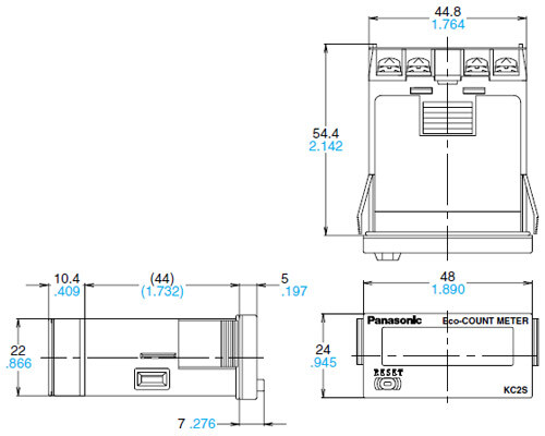
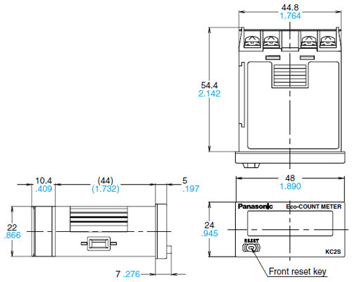
1.Main unit
One touch installation type(AKC2621/AKE2621)
Installation frame type(AKC2421/AKE2421)
2.Dedicated CT
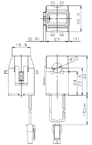
3.Trunk Cable
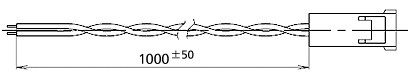
Note: The trunk cable connects the main unit and dedicated CT.It is included with the main unit.
Cautions For Use
1.Main unit
1) Reset input
(1) Never apply voltage to reset input. This can cause damage to the internal elements.
(2) Since the current flow is very small from reset input terminal 3, please use relays and switches with high contact reliabillity.
When inputting a reset by a transistor’s open collector use a transistor for small signals in which ICBO is 1μA or less and always input with no voltage.
(3) When wiring, try to keep all the input lines to the reset inputs as short as possible and avoid running them together with high voltage and power transmission lines or in a power conduit.
Note that power cable floating capacitance in excess of 500 pF (10m on 2 mm2 parallel cables) could cause malfunctions. Take particular care of inter-cable capacitance when using shielded cables.
2) How to reset multiple panel installation type units all at once.
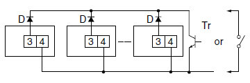
Note 1:Use the following as a guide for choosing transistors used for input (Tr).Leakage current < 1μΑNote 2:Use as small a diode (D) as possible in the forward voltage so that the voltage between terminals 3 and 4 during reset input meets the standard value (0.5V).(At IF = 20μA, forward voltage 0.1 V or less.)
2.Dedicated CT
1) Measured power is AC (50 Hz/60 Hz).
Will not function when used with DC power.
2) When clamping to the power cable to be measured, clamp only one of the live wires.
3) Avoid usage that bends the lead wire.
4) When clamping, make sure that no dust or other foreign matter intercedes between the clamp and contact. Foreign matter could impact detection sensitivity.
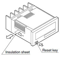
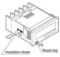
3.Insulation sheet
Before using, please pull and remove the insulation sheet in the direction of the arrow.
In consideration that the product might be stored for long periods without being used, an insulation sheet is inserted before shipping.
Remove the insulation sheet and press the front reset key.
Installation frame type
One-touch installation type
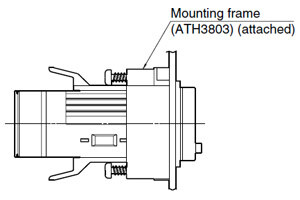
4.Waterproof construction
The operation part is constructed to prevent water from entering the unit and a rubber gasket is provided to prevent water from
entering the gap between the unit and the panel cutout.
There must be sufficient pressure applied to the rubber gasket to prevent water from entering.
Be sure to use the mounting screws when using the mounting frame (ATH3803).
Attaching the one-touch installation type to a panel will not waterproof the panel surface.
5.Do not use in the following environments
- 1) In places where the temperature changes drastically.
- 2) In places where humidity is high and there is the possibillity of dew. (When dew forms the display may vanish and other display errors may occur.)
6.Cautions regarding battery replacement
- 1) Remove wiring before replacing the battery.
You may be electrocuted if you come into contact to a part where high voltage is applied. - 2) Make sure you are not carrying a static electric charge when replacing the battery.
- 3) Battery replacement procedure
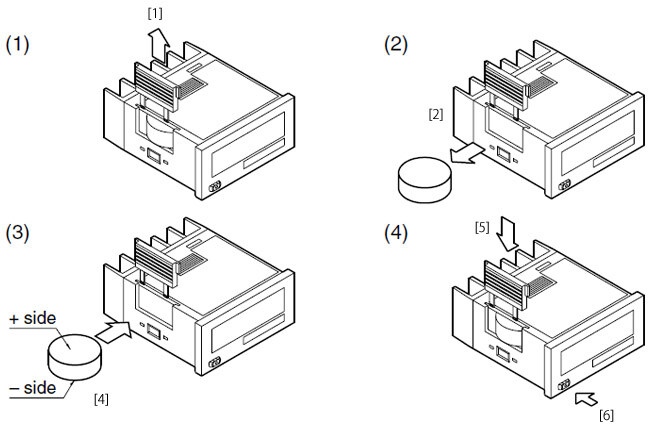
• Installation frame type
(1) Remove the battery cover [1] from the case.
(2) Remove the battery [2] from the side of the case.
The battery will come loose if you put the battery side face down and lightly shake the unit.
(3) Before inserting wipe clean the surface of the battery.
Insert the battery [4] with the + and – sides in the proper position.
(4) After replacing the battery return the battery cover [5] to the case. Verify that the hook of the battery cover is properly engaged.
Before using press the reset key [6] on the front.
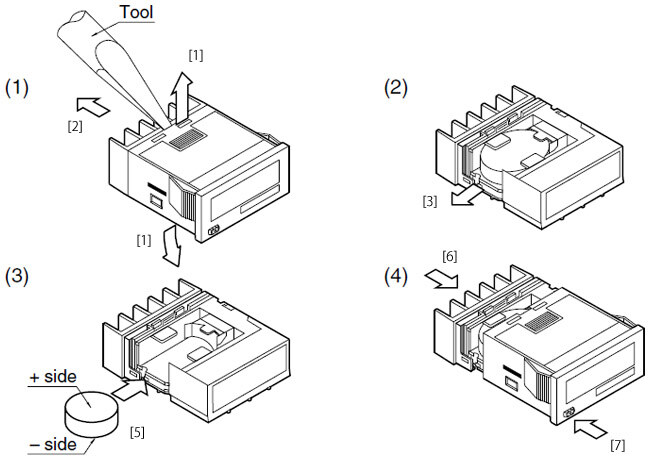
• One-touch installation type
(1) Using a tool remove the up/down hook of the case [1].
Pull the unit [2] away from the case.
(2) Remove the battery [3] from the side of the unit. Do not touch the display or other parts.
(3) Before inserting wipe clean the surface of the battery.
Insert the battery [5] with the + and – sides in the proper position.
(4) After replacing the batery return the unit [6] to the case. Verify that the hook of the case has properly engaged.
Before using press the reset key [7] on the front.