KR20 Wireless Unit (Discontinued Products)
Download
-
Discontinued Products
-
Specifications
-
Dimensions
-
Software
-
Cautions For Use
Ⅾiscontinued
Last time buy
December 19, 2014
Discontinued Products

Specifications
General specifications
| Item | Specifications | |
|---|---|---|
| RS485 type | I/O type | |
| Rated voltage | 12 to 24V DC | |
| Operating voltage range | 10.8 to 26.4V DC | |
| Current consumption | 150mA or less (During sending) | 200mA or less (During sending) |
| Inrush current | 23A (when 24V DC) | |
| Ambient temperature | -10 to +50°C | |
| Storage temperature | -20 to +70°C | |
| Ambient humidity | 30 to 85%RH (at 25°C non-condensing) | |
| Storage humidity | 30 to 85%RH (at 25°C non-condensing) | |
| Breakdown voltage (initial) | 500V AC for 1 min. (Between power terminal and FG/DSUB connector) | 500V AC for 1 min. (Between power terminal and FG/DSUB connector, Between power terminal and input/output terminal, Between input terminal and output terminal) |
| Insulation resistance (initial) | 100M ohm or more (at 500V DC mega) (Between power terminal and FG/DSUB connector) | 100M ohm or more (at 500V DC) (Between power terminal and FG/DSUB connector, Between power terminal and input/output terminal, Between input terminal and output terminal) |
| Vibration resistance | 10 to 55Hz 1cycle/min. Double amplitude of 0.75mm, 10min. on 3 axes | |
| Shock resistance | 98m/s2 or more, 4 times on 3 axes | |
| Noise immunity | 1000V [p-p] with pulse width 50ns, 1 μs (based on in-house measurements) (Power terminal) | |
| Overcurrent protection of power supply | Fuse (Rated current: 3.15A) | |
| Weight | Approx. 160g | |
Wireless specifications
| Item | Specifications | ||
|---|---|---|---|
| RS485 type | I/O type | ||
| Wave type | Direct sequence spread spectrum (DS-SS) | ||
| Transmission distance | Approx. 250 m outdoors* (straight, obstacle-free distance), Approx. 50 m indoors | ||
| Wave output | 6mW/MHz or less | ||
| Frequency | 2403.328MHz to 2480.128MHz | ||
| Number of channels | 76ch (Select with communication channel switch)*1 | ||
| Number of channels in same transmission area | 15 channels recommended (when select fixed channel)*2 | ||
| Transmission speed | 134kbps | ||
| Communication style | 1: N topology (N: 99 units max.) | ||
| Repeater function | 8 repeaters (Between master and slave) | ||
| Response time | - | OFF→ON | Max. 80ms*3 |
| ON→OFF | |||
* The main unit, standard antenna and antenna with cable are designed for indoor use.
If they are used outdoors, then take water-proof measures such as using plastic cases, etc.
Serial communication specifications (RS232C) *4
| Item | Specifications |
|---|---|
| Interface | Conforming to RS232C |
| Transmission distance | 15m |
| Transmission speed | 1200, 2400, 4800, 9600, 19200, 38400, 57600, 115200 bit/s (Selectable with MODE switch) |
| Communication method | Half-duplex |
| Synchronous system | Synchronous communication method |
| Transmission format | Stop bit: 1 bit, Parity: Not available/Available (odd/even), Data length: 7bit/8bit |
| Data buffer | 2048 bytes (Max. data byte size for send and receive one time) |
Serial communication specifications (RS485) (only AKR2002) *4
| Item | Specifications |
|---|---|
| Interface | Conforming to RS485 |
| Transmission distance | 1,200m |
| Transmission speed | 1200, 2400, 4800, 9600, 19200, 38400, 57600, 115200 bit/s (Selectable with MODE switch) |
| Communication method | Half-duplex |
| Synchronous system | Synchronous communication method |
| Transmission format | Stop bit: 1 bit, Parity: Not available/Available (odd/even), Data length: 7bit/8bit |
| Data buffer | 2048 bytes (Max. data byte size for send and receive one time) |
| Ending resistance | Approx. 120 ohm (built-in) (Terminal “E” and terminal “–” are shorted when ending.) |
| Number of connected units | Max. 31 |
Input specifications (only AKR2015 and AKR2045)
| Item | Specifications | |
|---|---|---|
| AKR2015 (Output NPN type) | AKR2045 (Output PNP type) | |
| Insulation method | Optical coupler | |
| Rated input voltage | 12 to 24 V DC (voltage input) | |
| Operating voltage range | 10.8 to 26.4 V DC | |
| Rated input current | Approx. 3mA/when 12 V, Approx. 6mA/when 24 V | |
| Points per common*5 | 8 points/common (Either positive or negative of input power supply can be connected.) | 6 points/common (Either positive or negative of input power supply can be connected.) |
| Input impedance | Approx. 4k ohm | |
| Operation indicator | LED display (green) | |
Output specifications (only AKR2015 and AKR2045)
| Item | Specifications | ||
|---|---|---|---|
| AKR2015 (Output NPN type) | AKR2045 (Output PNP type) | ||
| Insulation method | Optical coupler | ||
| Output type | Open collector (NPN) | Open collector (PNP) | |
| Rated load voltage | 12 to 24 V DC | ||
| Allowable load voltage range | 10.8 to 26.4 V DC | ||
| Max. load current | 0.3A | ||
| Max. inrush current | 1.5A | ||
| Points per common*5 | 9 points/common (Signal output, Communication error output) | 7 point/common (Signal output, Communication error output) | |
| Off state leakage current | 1 μA or less | ||
| On state voltage drop | 1.5 V DC or less | ||
| External power supply (+, – terminal) | Voltage | - | 10.8 to 26.4V DC |
| Current | - | Max. 60mA | |
| Surge absorber | Zener diode | ||
| Operation indicator | LED display | ||

Functions specifications
| Item | Specifications | |
|---|---|---|
| RS485 type | I/O type | |
| Setting function | • Operating mode change (SET, RUN, TEST) • Communication channel change (CH switch) • Unit No. change (UNIT No. switch) • Serial communication setup (MODE switch) • Slave registration • Initializing (Factory setting) | |
| - | Data holding (When communication error) | |
| Test function | Communication test: 3-stage LED display (With setting tool, it can do various communication tests such as changing data amount, including repeaters and so on. And it can measure an approximate communication time.) Field intensity monitor: 3-stage LED display (With setting tool, it can display and record a field intensity of each channel by numeric value.) | |
| LED display | • Distinguish master or slave (MASTER) • On communication, Power on (COM.) • On setting, Complete setting (SET) • Error, Alarm, Caution (ALARM) • Level indication (1, 2, 3: when using test function) | |
| - | I/O operating display (16 or 12 points + 1 point of communication error) | |
*1 Adding to the fixed channel, 76ch (00 to 4B), 89 group channel can be selected.
Group channel is the function that it selects connectable channel from several fixed channels automatically. When using repeater function, use with the fixed channel.
When using group channel, settable channel numbers are decreased in the same communication area and the communication time becomes longer.
*2 It is different according to the mounting conditions, when several channels are used in the same communication area, communication error might occur due to interference radio wave.
*3 There are no error without serial communication at 1:1 topology.
Response time: Time from input signal to input terminal to output from output terminal in connected equipment
When input signal is shorter than response time, there is a possibility not to transfer to output side.
*4 RS232C and RS485 are not used in the same time.
*5 In case simultaneously ON of input and output, input number and output number are restricted according to the ambient temperature.
Dimensions
- Unit: mm in
1.Main unit
Dimensions
General tolerance: ±1.0

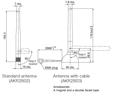
2.Antenna
Dimensions
General tolerance: ±1.0

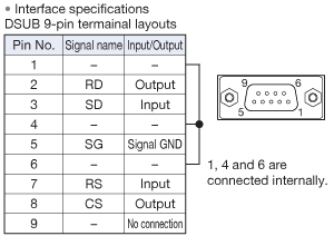
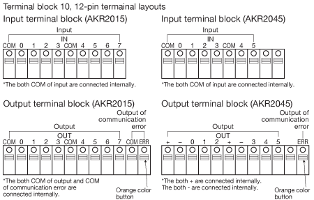
3.Termainal Layouts
Power supply connector

RS232C Connector

* In case without flow control, use DSUB 9 pin female-female straight cable to connect to the computer. If using male-female straight cable, use attached gender changer in main unit. (when using setting tool etc.)
RS485 terminal block (only AKR2002)

* 1 and 3, 2 and 4 are connected internally.* Shielded twisted-pair cable (connectable range: AWG26-20, cross-section area: 0.14-0.5mm2) is recommended. (stripped wire length is 9mm)* When using shielded cable, the grounding connection should have a resistance of less than 100 ohm, and grounded one end.* Connect between each unit by extending wiring in the transmission line.Cannot use branch connection.* At terminal unit, "E" terminal (No.5) should be shorted with "-" terminal (No.4). (Terminator connection)
I/O terminal block (only AKR2015 and AKR2045)

* Shielded cable (connectable range: AWG26-20,cross-section area: 0.14-0.5mm2) is recommended. Select the diameter that there is margin in the current capacity. (stripped wire length is 9mm)* When using shielded cable, the grounding connection should have a resistance of less than 100 ohm, and grounded one end.* Connect the wire with pushing the orange color button.
Software Download
Software are available for download.
*Membership registration is required to access/download this data.
>>Go to Data download.
Cautions For Use
1.When mounting, (wiring, adjustment etc.), be careful not to add static electricity to connector, switch and antenna.
2.Do not squeeze the switches or push buttons with an excessive force. Otherwise, they may be damaged.
Mounting
- Mount the unit as high as possible.
- Connect 2 of the antenna and the mounting direction is vertical for the ground.
- Antenna should be keep away from metal board. If antennas are mounted inside the control board, the wireless performance will decrease.
- Keep away from the place or line that noise might occur.
- Mount in the place where electric wave condition is good refer to field intensity monitor.
- When using several channels in the same communication area, check if there is no influence each other.
- 1.Do not place the units in the vicinity of radios or TVs. Otherwise, the reception may be impaired.
- 2.If nearby broadcasting or wireless stations emit radio waves with a high field intensity, then this wireless system may not be used.
- 3.This system uses frequencies on 2.4 GHz band for data communication. If there are other devices using the same frequency band in its vicinity, then the communication may be impaired due to interference.
- 4.In order to make the wireless performance better, pay attention to the below items.
Restrictions
Wired communication restrictions
・Separation of data sent on wire
The wireless unit detects the end of data sent on wire not by control codes such as "CR", etc., but by the idle time. Initially, if there is an idle time equivalent to 10 characters, then it will be deemed the end of data and the wireless unit will start communicating. Therefore, if consecutive data includes an idle time equivalent to 10 characters or more, then the data will be separated. However, if the idle time between two successive items of data is equivalent to 10 characters or less, then they will be deemed to be partial data and will not be sent correctly.

・Direction of communication between the master and slave (1:1 topology with repeaters or 1:N topology)
Command and response is assumed in the communication procedure. Set the master to a command sender and the slave to a response sender. Otherwise, the communication is impossible. If both units are set to command senders, then communication will not be possible.

・Command and response sequence
If commands are sent in succession, then define a sequence, in which a command is sent after the response to the previous command is returned. If a time-out is defined, then the time required for wireless communication must be taken into consideration. The time required for wireless communication may be extended depending on the communication environment. If the interval between two commands is fixed, then a command and a response may collide with each other.
Input signal time
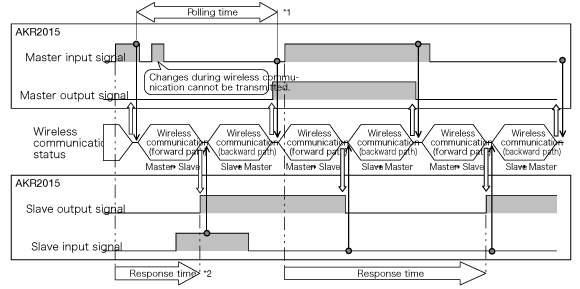
During 1:1 topology or 1:1 topology with repeaters for the I/O type , the input or output signals are not always monitored. They are monitored only immediately before wireless transmission and when their information is transmitted. In this case, if the input signal duration is shorter than the polling time*1, then it may not be transmitted to the output terminal. Therefore, in order to ensure that the input signal is transmitted, it must be held for the polling time or more.

*1 The polling time refers to a cycle for the master to continuously transmit (polling) data to a slave.*2 The response time refers to the time required for the signal inputted to the input terminal to be outputted from the output terminal of the partner unit.
Protocol for 1:N topology
| Communication protocol | RS485 type | I/O type | Restrictions | Remark |
|---|---|---|---|---|
| Yes | Yes | • The volume of data to be simultaneously transmitted must not exceed 2,048 bytes. • The time-out must be able to be extended. | *1 | |
| MODBUS ASCII | Yes | - | ||
| MODBUS RTU | Yes | - | ||
| GT Series Original | Yes | - | Screens cannot be transferred. | |
| Message Runner Original | Yes | - | Screens cannot be transferred. |
MEWTOCOL (Panasonic Electric Works)
*1 Operations using the PLC software are not supported.
*2 Use with 1:1 topology or 1:1 topology with repeaters for other protocols.
To prevent from interference with the other wireless station (Japan only)
- 1.Before using this unit, please confirm that in-plant radio station to identify mobile object, specified low power radio station and amateur radio station are not managed.
- 2.When some cases of harmful electric wave interference occurred from this unit to an in-plant radio station to identify mobile object, change the using frequency immediately or stop discharging the electric wave. After that please contact us to consult measures to avoid interference (for example, setting of partition).
- 3.When any other troubles such as harmful electric wave interference occurred from this unit to a specified low power radio station or an amateur radio station or an amateur radio station, please contact us.
Actual indication

* Please put the attached label “Caution for using wireless unit” near the setting place.
(1) 2,4 : 2.4GHz band electric wave is used. (2) DS : Modulation method is direct sequence type. (3) 4 : Intended interference distance is 40m. (4) Bar : All bands are used and possible to avoid the band of machine to identify mobile object.Countries where the use of KR20 has been authorized
![]()
*1 From March 31, 2013, this product will not be available in China.
*2 In France, this product must not be used outdoors. Please use it indoors only.
[Note] Countries where the use of KR20 has been authorized
Products with the indication label affixed to their rear side As of May 2008, the use of KR20 has been authorized in the following countries:
Japan, China*1, Thailand, 25 European countries (Austria, Belgium, Czech Republic, Denmark, Estonia, Finland, France*2, Germany, Greece, Hungary, Iceland, Ireland, Italy, Lithuania, Malta, Norway, Poland, Portugal, Slovakia, Slovenia, Spain, Sweden, Switzerland, UK, Netherlands)
Compliance for EN standard
Obtained the European wireless certification (EN300 328)
In order to comply with EN standard, use this product in following condition.
・ When installing this product to wall, install it on a DIN rail.
・ Use power supply cord that is less than 3m.
・ For communication cable (RS232C or RS485), use shielded cable, and connect one end of shield wire to ground. And use ferrite core (correspond to TDK: ZCAT2035-0930) in the communication cable (RS232C or RS485) of wireless unit side. (Turn numbers: 2T)