Discontinued Products
Number System
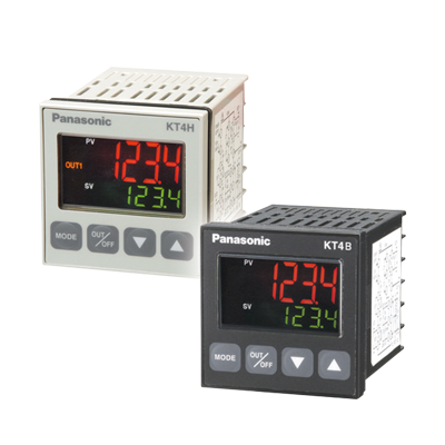
KT4H series (Ash grey)

Notes:
1) CT1 or CT2 for current transformer is provided as an accessory when heater burnout alarm is added.
2) Under some conditions, option functions (shaded items) may not be available; please check the “Description” of the above table for non-functioning
circumstances
Model No. search method
Example: When the optional functions (heating/cooling: relay contact, communication function: serial communication) are added on to the basic function
• Model No.: AKT4H1111101
KT4B series (Black)

Notes:
1) Please inquire if you need specifications not included in the model numbers above. On our website, it is easy to find products by model number selection
or by searching for specifications.
2) Use RS-485 for serial communication.
Dimensions
- Unit: mm in
Panel cut-out dimensions
When installing in series
General tolerance : ±1.0±0.39Note:If longitudinal or lateral close mounting is used for the controller, IP66 specification (Dust-proof/Drip-proof) may be compromised, and all warranties will be invalidated.
CT1
Current transformer (CT) (for 5, 10, and 20A)
CT2
Current transformer (CT) (for 50 A)
Note:
Current transformer CT1 or CT2 is included (only with KT7 and KT4H)
when heater burnout alarm function is added.
AKT4H801
Terminal cover (for KT4H / KT4B / KT4R)
AKW4822
Mounting frame (for KT4R / KT4H / KT4B)
AKT4H820
Tool cable(for KT4H / KT4B)
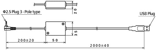
AKT4810
Shunt resistor
Wiring/ Connection
External Connection Diagram
POWER SUPPLY : Power supply voltage
EVT1 : Alarm output 1
EVT2 : Alarm output 2 (optional) or heater burnout alarm output (optional)
OUT1 : Control output or heating output (optional)
OUT2 : Cooling output (optional)
TC : Thermocouple input
RTD : Resistance temperature detector input
DC : DC current input (DCA) or DC voltage input (DCV)
(For DC voltage input, + side connection terminal differs depending on the voltage. Also, for DC current input, connect shunt resistor between No. (10) and (12) terminals.)
T1 : Current transformer input 1 (optional: for single phase and three phases)
CT2 : Current transformer input 2 (optional: for three phases)
DI : Contact input (optional)
RS-485 : Serial communication RS-485 (optional)
Communication Function Connection Diagram(PLC Connection Diagram)
Notes: 1)Shield wireTo prevent current flow along shield sections, ground one end of the shield wire.(If both ends of the shield section are grounded, a closed circuit with the earth will form and electricity flowing through the shield wire will cause increased susceptibility to noise.)2)Terminating Resistors (Terminators)The KT4H / KT4B series has a built-in pull-up resistor or pull-down resistor.For this reason, do not connect the terminating resistor on the communication line.
Cautions For Use
Mounting
Please install vertically in order to satisfy the IP66 specification for dust and splash proofing.
The possible control panel plate thickness for installation is between 1 to 5 mm 0.039 to 0.197 in.
(1)Insert the unit from the front of the control panel.
(2)Push the mounting frame fully into contact with the paneland tighten the screws. (Screw tightening torque: 0.05 N·m to 0.06 N・m)
Part description
Note: Color selection is the same for each size.
(1)Action indicators (backlight: Orange) ℉℃ : Lights respectively when temperature unit℉/℃ is selected. T/R : Lights during serial communication (optional) TX output. AT : Flashes during auto-tuning or auto-reset. OUT1 : Lights when control output is ON or heating output (optional)is ON.
For DC current output type, it flashes corresponding to the
manipulated variable in 0.25 second cycles. OUT2 : Lights when cooling output (optional) is ON. EVT1 : Lights when alarm output 1 is ON. EVT2 : Lights when alarm output 2 (optional) is ON or heater burnout
alarm output (optional) is ON. LOCK : Lights when lock 1, lock 2 or lock 3 is selected. (2)MEMO display : Indicates the set value memory number. (backlight: Green) (3)PV display : Indicates the process value (PV). (backlight: Red / Orange /
Green) (4)SV display : Indicates the set value (SV). (backlight: Green) (5)Mode key : Selects the setting mode and registers the set value. (6)OUT/OFF key : The control output ON / OFF or auto / manual control
function can be switched. (7)Increase key : Increases the numeric value. (8)Decrease key : Decreases the numeric value. (9)Tool connector : By connecting the dedicated cable, the following operations can be conducted from the external computer.
- Reading and setting of SV, PID and various set values
- Reading of PV and action status
- Function change
Notes on site selection
This controller is intended to be used in the following environment (IEC 61010-1)
Mount the controller in a place with:
- Overvoltage category II and Pollution degree 2
- A minimum of dust, and an absence of corrosive gases
- No flammable, explosive gases
- Few mechanical vibrations or shocks
- No exposure to direct sunlight, an ambient temperature of -10 to 55 ℃ 14 to 131 ℉ that does not change rapidly. (When installing inside a panel, make particular allowance for heat dissipation. Avoid installation in situations such as above equipment that generates heat.)
- Locations in which temperature rapidly changes may cause condensation.
- Locations or atmospheres in which benzine, thinners, alcohol, or other organic solvents are present, or in which ammonia, sodium hydroxide, or other strong alkaline substances may adhere.
- Locations susceptible to direct impact or the transmission of vibrations, or where splashing with water is possible.
- In the proximity of equipment in which large switching surges occur or near high-voltage cables, high-voltage equipment, power lines, power equipment, ham radio transmitters, or equipment containing these or similar devices.
- An ambient non-condensing humidity of 35 to 85 % RH
- No large capacity electromagnetic switches or cables through which large current is flowing
- No water, oil or chemicals or where the vapors of these substances can come into direct contact with the controller
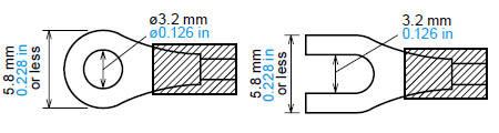
Notes on wiring
| Wire-pressed terminal | Company name | Type name | Fastening torque |
|---|---|---|---|
| Fork type | NICHIFU Co., Ltd. | 1.25Y-3 | 0.6 N•m Max. 1.0 N•m. |
| J.S.T. Mfg. Co., Ltd. | VD1.25-B3A | ||
| Round type | NICHIFU Co., Ltd. | 1.25-3 | |
| J.S.T. Mfg. Co., Ltd. | V1.25-3 |
- The terminal block of KT4R / KT8R / KT9R / KT4H / KT4B series are designed to be wired from the left side (The terminal of KT2 series are designed to be wired from the upper and lower direction). The lead wire must be inserted from the left side of the terminal, and fastened by the terminal screw. Use a wirepressed terminal with insulation sleeve that fits to the M3 screw.
- Terminal screw fastening torque is 0.6 N·m to 1.0 N·m (for KT4R / KT8R / KT9R / KT4H / KT4B series). For KT7 series by M3 screw is less than 0.5 N·m and by M2 screw is less than 0.25 N·m respectively.
- Use a thermocouple and compensating lead wire according to the sensor input specification of the controller.
- Use a 3-wire system of RTD according to the sensor input specification of the controller.
- This controller has no built-in power switch, circuit breaker and fuse. Therefore, it is necessary to install them in the circuit near the external controller. (Recommended fuse: Time-lag fuse, rating voltage 250 V AC, rating current 2 A)
- In the case of 24 V AC / DC power supply, do not confuse the polarity when it is DC.
- With the relay contact output type, use the relay externally according to the capacity of the load to protect the built-in relay contact.
- When wiring, keep input wire (Thermocouple, RTD, etc.) away from power source wire and load wire.
- Turn the power supply to the instrument off before wiring or checking. Working or touching the terminal with the power switched on may result in electric shock which could cause severe injury or death.
- Do not drop wire chips into the holes of vent when wiring.
- To prevent the controller from harmful effects of unexpected high level noise, it is recommended that a surge absorber be installed between the electromagnetic switch coils.
Notes on mounting
- Do not use excessive force while screwing in the mounting frame and mounting bracket of KT4R / KT8R / KT9R / KT4H / KT4B series.
For KT8R / KT9R series, recommended torque is approximately 0.1 N·m.
For KT4H / KT4B series, recommended torque is approximately 0.05 to 0.06 N·m.
For KT4R series, recommended torque is approximately 0.15 N·m. - When mounting the KT7 series to the DIN rail, mount it in a lateral direction. Make sure a click is audible when fixed into place.
Optional heater burnout alarm output
(for KT7 / KT4H series)
- This alarm output is not available for detecting heater current under phase control.
- Use the current transformer (CT) provided, and pass one lead wire of the heater circuit into the hole of CT.
- When wiring, keep CT wire away from power source wire and load wire to avoid external interference.
- In three phase installations for KT4H series, ensure that R, S and T are each connected to a 2-line CT that connects with CT1 [(13) - (14)] and CT2 [(14) - (15)] terminals.