Discontinued Products
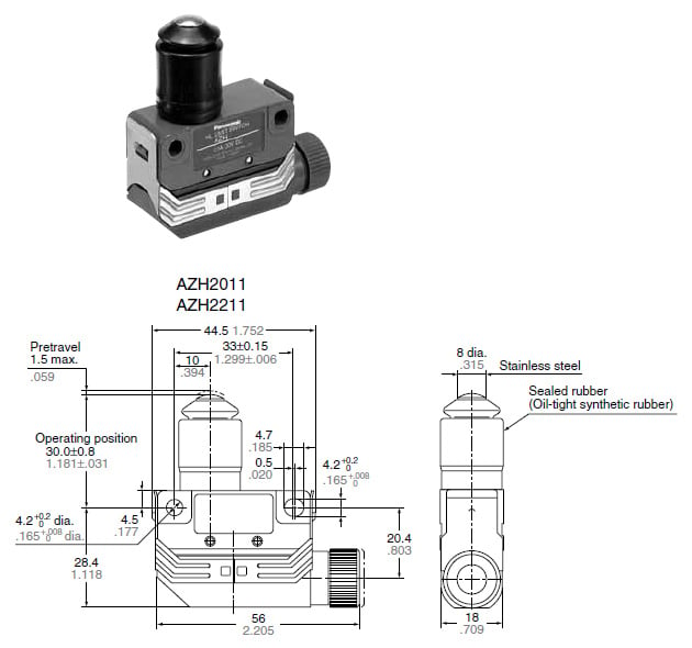
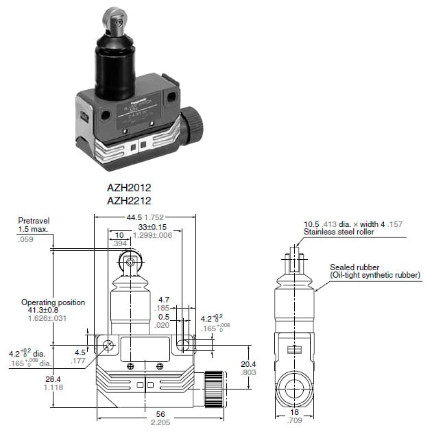
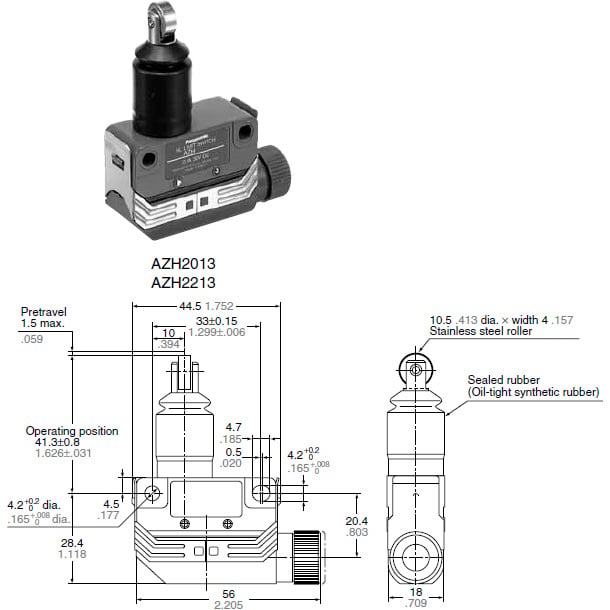
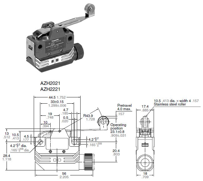
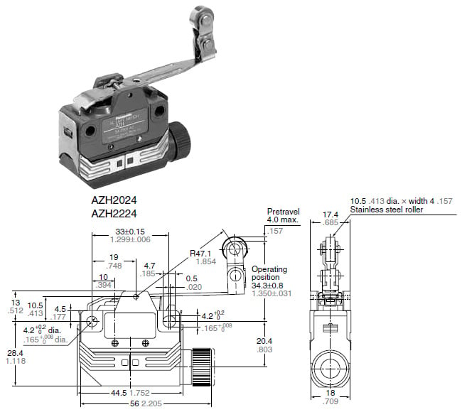
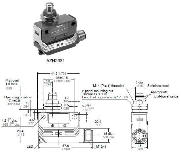
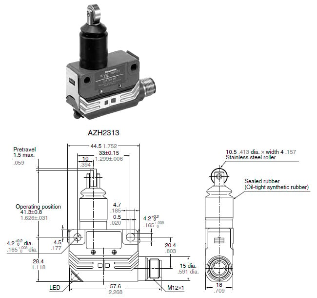
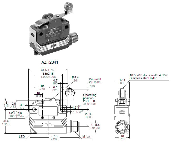
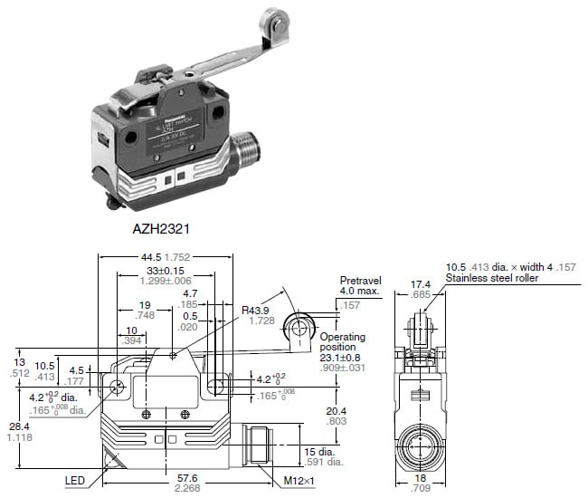
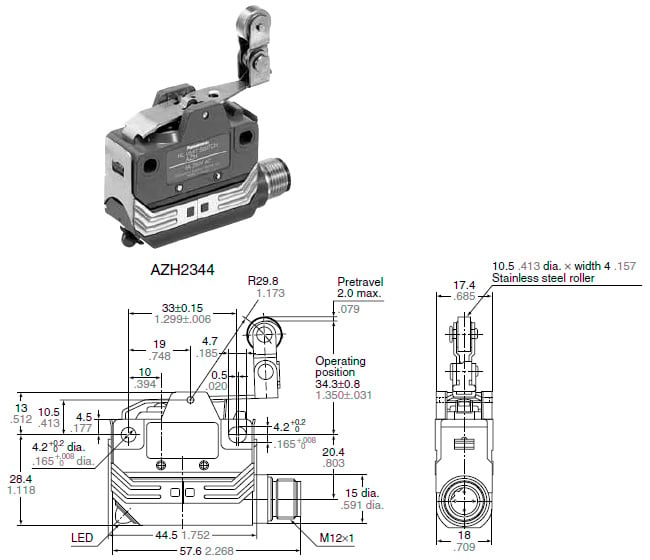
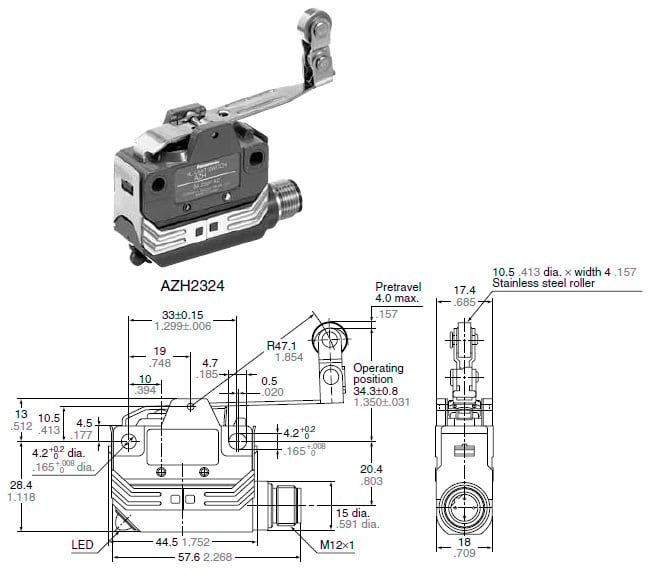
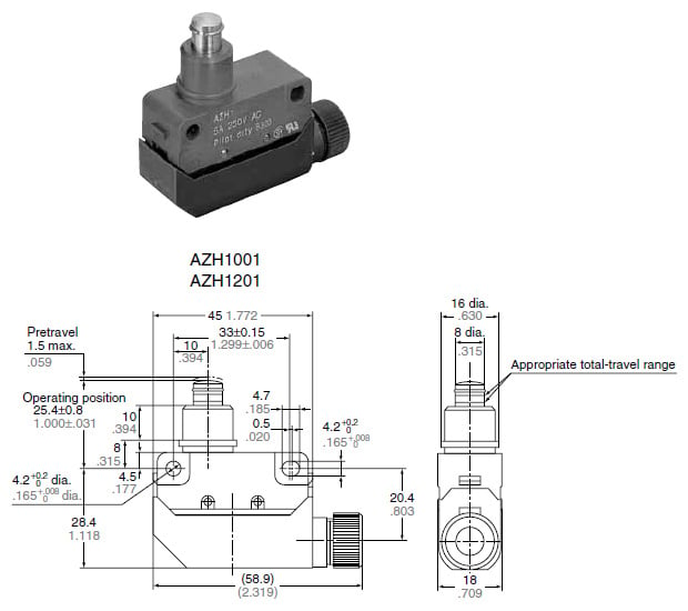
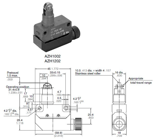
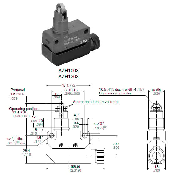
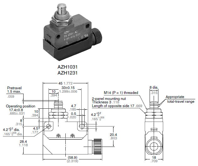
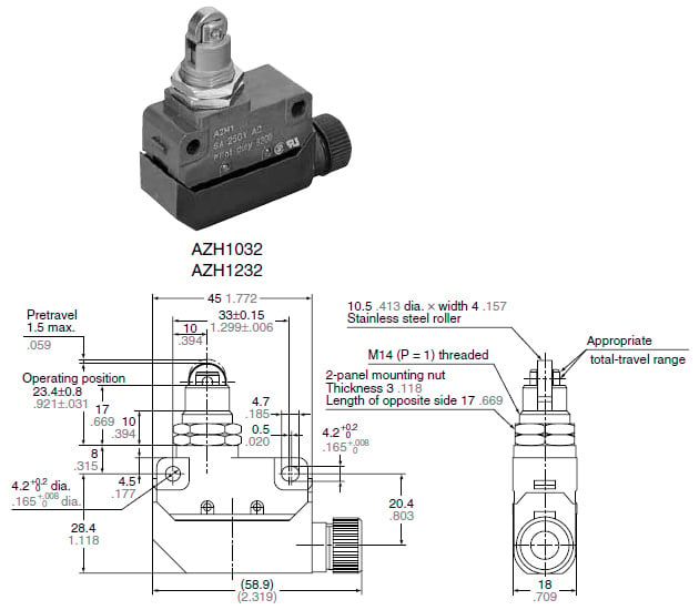
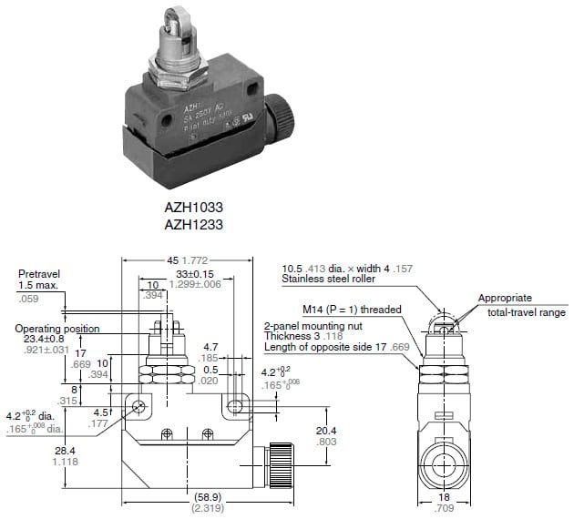
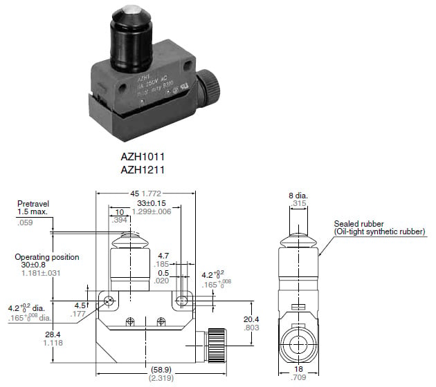
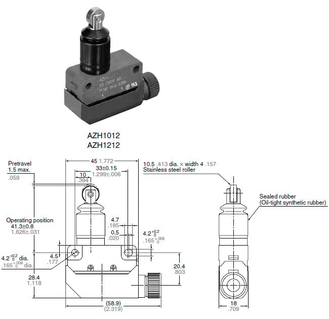
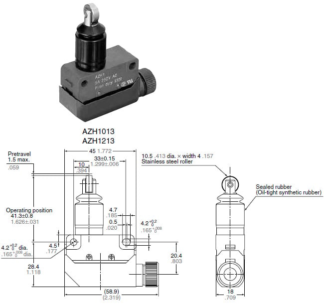
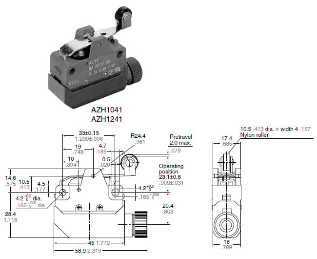
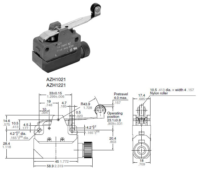
Dimensions
- Unit: mm in
General tolerance : ±0.4 ±0.016
Die cast case
Screw terminal type
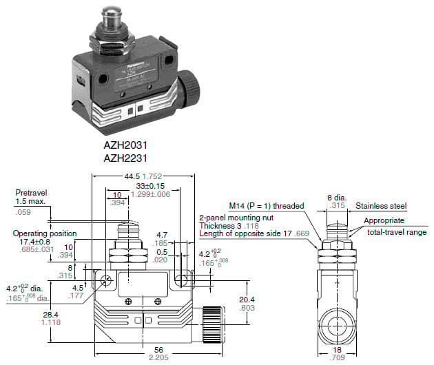
Panel mount push plunger
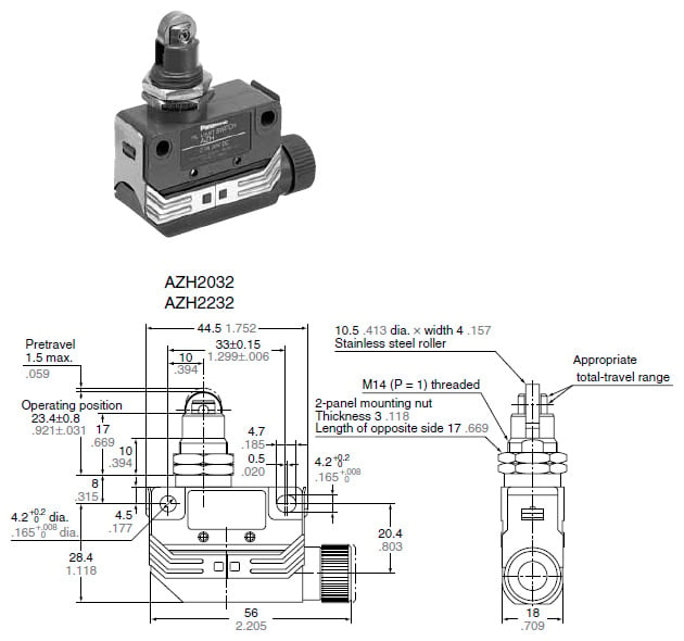
Panel mount roller plunger
Panel mount cross roller plunger

Sealed push plunger
Sealed roller plunger
Sealed cross roller plunger
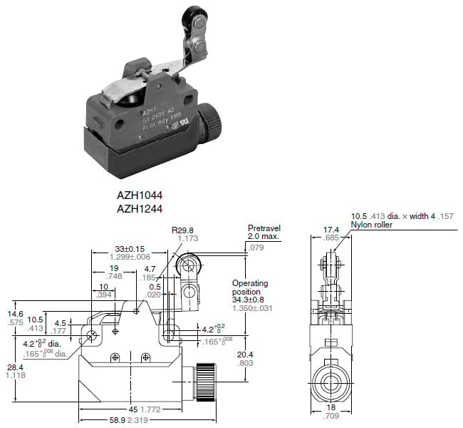
Short roller lever
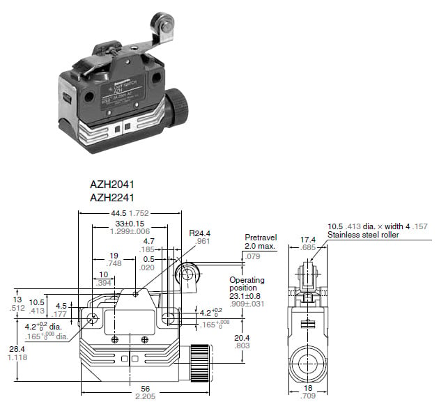
Roller lever
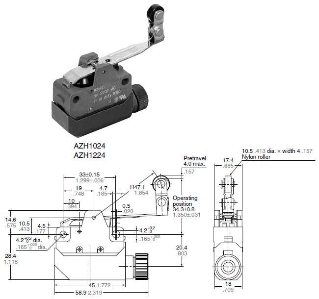
One-way short roller lever
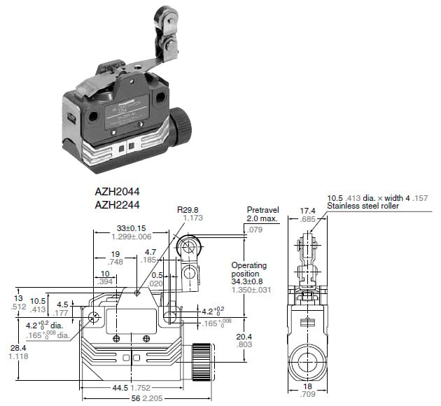
One-way roller lever
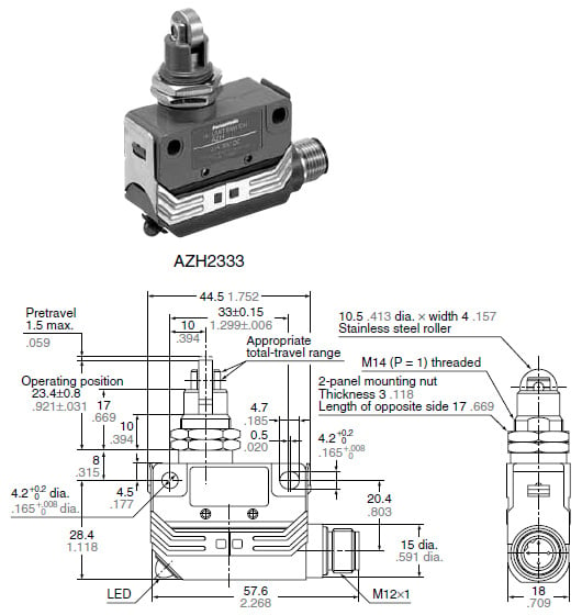
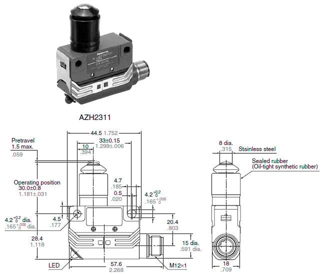
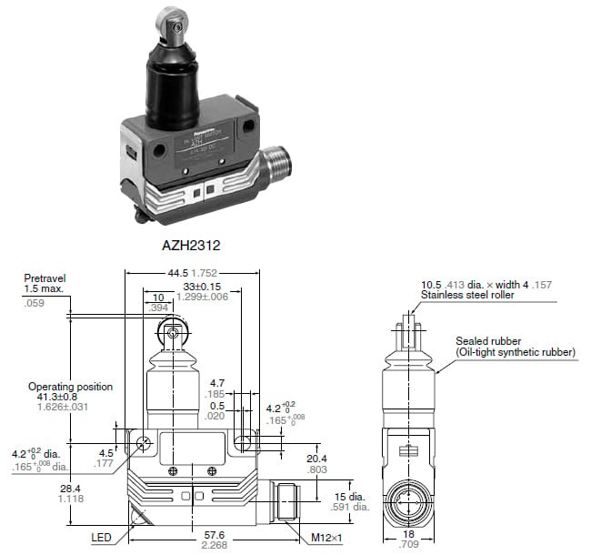
Connector type
Panel mount push plunger
Panel mount roller plunger
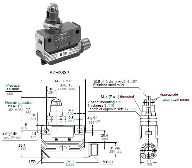
Panel mount cross roller plunger
Sealed push plunger
Sealed roller plunger
Sealed cross roller plunger
Short roller lever
Roller lever
One-way short roller lever
One-way roller lever
Plastic case
Push plunger
Roller plunger
Cross roller plunger
Panel mount push plunger
Panel mount roller plunger
Panel mount cross roller plunger
Sealed push plunger
Sealed roller plunger
Sealed cross roller plunger
Short roller lever
Roller lever
One-way short roller lever
One-way roller lever
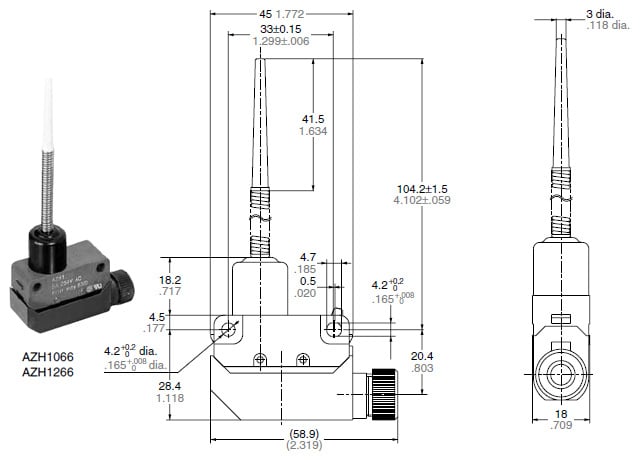
Flexible
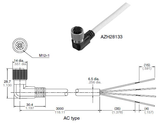
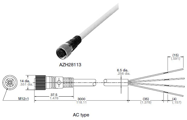
Cable connected cord
Straight type
Angle type