LH2H Hour Meters (Discontinued Products)
Download
-
Discontinued Products
-
Rating/ Performance
-
Dimensions
-
Cautions For Use
Ⅾiscontinued
Last time buy (JST)
June 30, 2023
We are sorry, the products have been discontinued. Please refer to the details of the discontinued products and the recommended substitutes list below.
Discontinued Products

Rating/ Performance
Panel Mounting Type
| Type | Standard type | Backlight type | Standard type | ||
|---|---|---|---|---|---|
| item | Non-voltage input | Voltage input | Voltage input | Free voltage type | |
| No. digits | 7 digits | ||||
| External power supply | Not required (built-in battery) | ||||
| Measurement time range | 0 to 999999.9h/0 to 3999d23.9h (Switchable by switch) 0 to 999h59m59s/0 to 9999h59.9m (Switchable by switch) Separate product type | ||||
| >Start input | >Min. input signal width | 200ms | |||
| Input method (signal) | Non-voltage input using contacts or open collector connection | High level: 4.5 to 30 V DC Low level: 0 to 2 V DC | High level: 24 to 240 V AC/DC Low level: 0 to 2.4 V AC/DC | ||
| Input impedance | When shorted: Max. 10 kΩ When open: Max. 750 kΩ | Approx. 4.7 kΩ | - | ||
| Residual voltage | Max. 0.5 V | - | - | ||
| Reset input | Min. input signal width | 100ms | |||
| Input method (signal) | Non-voltage input using contacts or open collector connection | High level: 4.5 to 30 V DC Low level: 0 to 2 V DC | Non-voltage input using contacts or open collector connection | ||
| Input impedance | When shorted: Max. 10 kΩ When open: Max. 750 kΩ | Appox. 4.7 kΩ | When shorted: Max. 10 kΩ When open: Max. 750 kΩ | ||
| Residual voltage | Max 0.5 V | - | Max 0.5 V | ||
| Display method | 7-segment LCD | 7-segment LCD With green/red backlight | 7-segment LCD | ||
| Breakdown voltage (initial) | Between charged and uncharged parts: 1,000 V AC for 1 minute. | Between charged and uncharged parts: 2,000 V AC for 1 minute. | |||
| Insulation resistance (initial) | Min. 100 MΩ (measured at 500 V DC) Measurement location same as for break down voltage. | ||||
| Backlight power | - | 24 V DC (±10%) | - | ||
| Protective construction (Note) | IEC Standard IP66 (only panel front: when using rubber gasket) | ||||
| Accessories (Note) | Rubber gasket, mounting bracket | ||||
| Battery life | 10 years (at 25°C/ 77°F) | ||||
Note)Only for installation frame type.
PC Board Mounting Type
| Type | PC board mounting type | ||
|---|---|---|---|
| Item | |||
| Input method | Non DC voltage input | ||
| No. digits | 7 digits | ||
| Rated operation voltage | 3 V DC | ||
| Allowable operation voltage range | 2.7 to 3.3 V DC | ||
| Current consumption | Max. 20 μA (max. 200 μA during reset input) | ||
| Measurement time range | 0 to 999999.9h | 0 to 9999h59.9m | |
| Start input | Min. input signal width | 200ms | |
| Input method | Non-voltage input using contacts or open collector connection | ||
| Input impedance | When shorted: Max. 10 kΩ When open: Max. 750 kΩ | ||
| Residual voltage | Max. 0.5 V | ||
| Reset input | Min. input signal width | 10ms | |
| Input method | Non-voltage input using contacts or open collector connection | ||
| Input impedance | When shorted: Max. 10 kΩ When open: Max. 750 kΩ | ||
| Residual power | Max. 0.5 V | ||
| Break down voltage (initial) | Between charged and uncharged parts: 1,000 V AC for 1 minute. | ||
| Insulation resistance (initial) | Min. 100 MΩ (measured at 500 V DC) Measurement location same as for break down voltage. | ||
Common
| Type | Panel mounting/PC board mounting types | |
|---|---|---|
| Item | ||
| Time accuracy | ±100 ppm (25°C/ 77°F) | |
| Vibration resistance | Functional | 10 to 55 Hz (1 cycle/min.), single amplitude: 0.15 mm (10 min. on 3 axes) |
| Destructive | 10 to 55 Hz (1 cycle/min.), single amplitude: 0.375 mm (1 hr. on 3 axes) | |
| Shock resistance | Functional | Min. 98 m/s2 (4 times on 3 axes) |
| Destructive | Min. 294 m/s2 (5 times on 3 axes) | |
| Operation temperature | --10 to +55°C/ +14 to +131°F (without frost or dew) | |
| Storage temperature | --25 to +65°C/ --13 to +149°F (without frost or dew) | |
| Ambient humidity | 35 to 85% RH (non-condensing) | |
Explanation of Operation
1.Time measuring takes place when the start input is ON.
2.When the elapsed (measured) time reaches full scale it returns to "0", and then measuring starts again from "0".
3.When reset input is ON, the display becomes "0". You cannot measure during reset input.
For PC board mounting type the display disappears while the reset input is ON; however, the display reads "0" when the reset input turns OFF.
4.Press the front reset button if you want to perform a manual reset (for panel installation type)

Dimensions
- Unit: mm in
1.Panel Mounting Type
1.One-touch installation type
Dimensions
General tolerance : ±1.0 ±0.39

Panel installation diagram
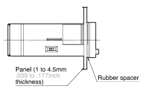
Note) When installing to a 4.5mm/ .177inch thick panel, remove the rubber spacer first.
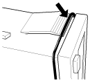
When installing the one-touch installation type model, make sure that the installation spring does not pinch the rubber gasket.
To prevent the installation spring from pinching the rubber gasket:
1.Set the rubber gasket on both ends of the installation spring(left and right).
2.Confirm that the installation spring is not pinching the rubber gasket, and then insert and fix the installation spring in place from the rear of the timer unit.
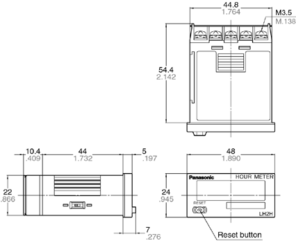
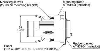
2.Installation frame type
Dimensions
General tolerance : ±1.0 ±0.39
Panel mounting diagram
Panel cut-out dimensions
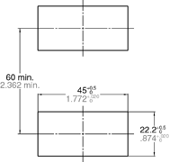
The standard panel cut-out is shown below.Use the mounting frame (ATH3803) and the rubber packing (ATH3804).(Only installation frame type.)
For connected installation
(sealed installation)
(Only installation frame type.)

Notes)1.Suitable installation panel thickness is 1 to 4.5 mm/ .039 to .177 inch.2.Waterproofing will be lost when installing repeatedly (sealed installation).
Terminal layout and wiring diagrams
1.Standard type
| Non voltage input type | Voltage input type | Free voltage input type |
|---|---|---|
|
|
|
2.Backlight type
| Voltage input type |
|---|
|
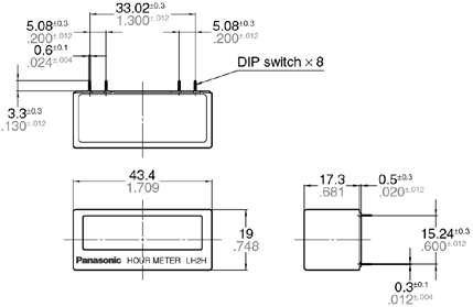
2.PC Board Mounting Type
External dimensions
General tolerance: ±1.0 ±.039
PC board pattern (BOTTOM VIEW)
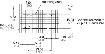
Note: The AXS212811K is recommended as a compatible connection socket.
Terminal layout and wiring diagrams

Cautions For Use
- Terminal layout and wiring diagrams
- LH2H Hour Meter Cautions for Use
- Precautions in using the LH2H Series
Terminal layout and wiring diagrams
Standard type
| Non voltage input type | Voltage input type | Free voltage input type |
|---|---|---|
|
|
|
Backlight type
| Voltage input type |
|---|
|
Terminal layout and wiring diagrams

LH2H Hour Meter Cautions for Use
Non-voltage input type
For both panel mounting and PC board mounting types
1.Never apply voltage to the non-voltage input type.
This will damage the internalelements.
2.Since the current flow is very small from the start input and reset input terminals ((1) and (3) on the panel mounting type and (15) to (17) and (26) to (26) on the PC board mounting type) please use relays and switches with high contact reliability. When inputting with an open collector of a transistor, use a transistor for small signals in which ICBO is 1 μA or less and always input with no voltage
3.When wiring, try to keep all the input lines to the start and reset inputs as short as possible and avoid running them together with high voltage and power transmission lines or in a power conduit. Also, malfunctions might occur if the floating capacitance of these wires exceeds 500 pF (10 m 32.808 ft. for parallel wires of 2 mm2). In particular, when using shielded wiring, be careful of the capacitance between wires.
PC board mounting type
1.For external power supply use manganese dioxide or lithium batteries(CR type: 3V).
2.Always reset after external power is applied and confirm that the display reads "0".
3.Make the wiring from the battery to the hour meter unit as short as absolutely possible. Also, be careful of polarity.
4.Calculate battery life with the following formula.
t = A / I
t:battery life [h]
I:LH2H current consumption [mA]
A:battery capacity until minimum operation voltage is reached [mAh]
5.Hand solder to the lead terminal. Do not dip solder. With the tip of the soldering iron at 300℃ 572℉ perform soldering within 3 seconds (for 30 to 60 W soldering iron).
Voltage input type
1.Be aware that applying more than 30 V DC to start input terminals (1) and (2), and reset input terminals (3) and (4) will cause damage to the internal elements.
2.For external resetting use H level (application of 4.5 to 30 V DC) between reset terminals (3) and (4) of the rear terminals. In this case, connect + to terminal (3) and -- to terminal (4). This is the valid polarity; therefore, the hour meter will not work if reversed.
3.When wiring, try to keep all the input lines to the start and reset inputs as short as possible and avoid running them together with high voltage and power transmission lines or in a power conduit. Also, malfunctions might occur if the floating capacitance of these wires exceeds 500 pF (10 m/ 32.808 ft. for parallel wires of 2 mm2).
Free voltage input type
1.Use start input terminals (1) and (2) for free voltage input and reset input terminals (3) and (4) for non-voltage input.
2.Be aware that the application of voltage that exceeds the voltage range of the H level to the start input terminal, and the application of voltage to the reset input terminal, can cause damage to the internal elements.
3.Since the current flow is very small from reset input terminal (3), please use relays and switches with high contact reliability.
4.When inputting a reset with an open collector of a transistor, use a transistor for small signals in which ICBO is 1 μA or less and always input with no voltage.
5.To reset externally, short reset input terminals (3) and (4) on the rear.
6.Input uses a high impedance circuit; therefore, erroneous operation may occur if the influence of induction voltage is present. If you plan to use wiring for the input signal that is 10 m 32.808 ft. or longer (wire capacitance 120 pF/m at normal temperature), we recommend the use of a CR filter or the connection of a bleeder resistor.
How to reset multiple panel mounting type counters all at once (input is the same for count)
Non-voltage input type
Notes)
1.Use the following as a guide for choosing transistors used for input (Tr). Leakage current < 1 μA
2.Use as small a diode (D) as possible in the forward voltage so that the voltage between terminals 3 and 4 during reset input meets the standard value (0.5 V).
(At IF = 20 μA, forward voltage 0.1 and higher.)

Note)Make sure that H (reset ON) level is at least 4.5V
Backlight luminance
To prevent varying luminance among backlights when using multiple Backlight types, please use the same backlight power supply.

Acquisition of CE marking
Please abide by the conditions below when using in applications that comply with EN 61010-1/IEC 61010-1
- 1.Ambient conditions
- Overvoltage category II, pollution level 2
- Indoor use
- Acceptable temperature and humidity range: -10 to +55℃, 35 to 85%RH (with no condensation at 20℃)
- Under 2000 m elevation
- 2.Use the main unit in a location that matches the following conditions.
- There is minimal dust and no corrosive gas.
- There is no combustible or explosive gas.
- There is no mechanical vibration or impacts.
- There is no exposure to direct sunlight.
- Located away from large-volume electromagnetic switches and power lines with large electrical currents.
- 3.Connect a breaker that conforms to EN60947-1 or EN60947-3 to the voltage input section.
- 4.Applied voltage should be protected with an overcurrent protection device
(example: T 1A, 250 V AC time lag fuse) that conforms to the EN/IEC standards. (Free voltage input type)
Terminal connection
Tighten the terminal screws with a torqueof 0.8 N?cm or less.
Precautions in Using The LH2H Series
Insulation sheet
Before using a panel mounting type, please pull and remove the insulation sheet in the direction of the arrow.
In consideration that the product might be stored for long periods without being used, an insulation sheet is inserted before shipping.
Remove the insulation sheet and press the front reset button.


Waterproof construction
LH2H hour meter (installation frame type)
The operation part of the panel installation type (installation frame type) is constructed to prevent water from entering the unit and a rubber gasket is provided to prevent water from entering the gap between the unit and the panel cutout.
There must be sufficient pressure applied to the rubber gasket to prevent water from entering.
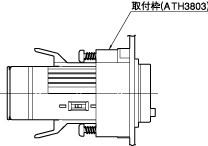
Be sure to use the mounting screws when installing the mounting frame (ATH3803).
Note:The one-touch installation type is not waterproof

LH2H preset hour meter
- 1.When using the waterproof type (IP66: panel front only), install the hour meter to the front plate with mounting frame ATH3803 (sold separately) and rubber gasket ATH3804 (sold separately).
Be sure to tighten using mounting screws.

*When installing the mounting frame and rubber gasket please remove the pre-attached o-ring.
- 2.Panel installation order
- 1.Remove o-ring.
- 2.Place rubber gasket.
- 3.Insert hour meter into panel.
- 4.Insert mounting frame from the rear.
- 5.Secure with mounting screws (two locations)
Do not use in the following environments
- 1.In places where the temperature changes drastically.
- 2.In places where humidity is high and there is the possibility of dew
(When dew forms the display may vanish and other display errors may occur.)
Conditions of use
- 1.Do not use on places where there is flammable or corrosive gas, lots of dust, presence of oil, or where the unit might be subject to strong vibrations or shocks.
- 2.Since the cover is made of polycarbonate resin, do not use in places where the unit might come into contact with or be exposed to environments that contain organic solvents such as methyl alcohol, benzene and thinner, or strong alkali substances such as ammonia and caustic soda.
Cautions regarding battery replacement
- 1.Remove wiring before replacing the battery.
You may be electrocuted if you come into contact to a part where high voltage is applied. - 2.Make sure you are not carrying a static electric charge when replacing the battery.
- 3.Battery replacement procedure
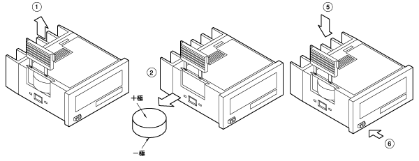
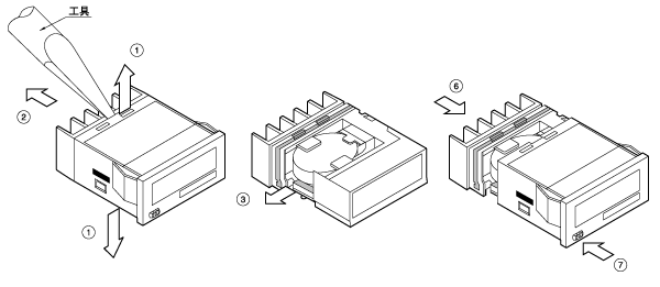
For LH2H hour meter (one-touch installation type)
- 1.Remove the up/down hook of the case using a tool.
- 2.Pull the unit away from the case.
- 3.Remove the battery from the side of the unit. Do not touch the display or other parts.
- 4.Before inserting wipe clean the surface of the new battery.
- 5.Insert the new battery with the "+" and "–" sides in the proper position.
- 6.After replacing the battery, return the unit to the case. Verify that the hook of the case has properly engaged.
- 7.Before using, press the reset button on the front.

For LH2H hour meter
(installation frame type)
- 1.Remove the battery cover from the case.
- 2.2) Remove the battery from the side of the case. The battery will come loose if you put the battery side face down and lightly shake the unit.
- 3.Before inserting wipe clean the surface of the new battery.
- 4.Insert the new battery with the "+" and "–" sides in the proper position.
- 5.After replacing the battery, return the battery cover to the case. Verify that the hook of the battery cover is properly engaged.
- 6.Before using press the reset button on the front.

使用上のご注意
1.無電圧入力タイプ
パネル取付タイプ、P板取付タイプ共通
- 無電圧入力タイプには絶対に電圧を印加しないでください。内部素子破壊の原因になります。
- スタート入力、リセット入力端子(パネル取付タイプは(1)、(3)端子、P板取付タイプは(15)-(17)、(26)-(28)端子)から流出する電流は微少のため、使用する接点は接触信頼性の良いリレーやスイッチをご使用ください。トランジスタのオープンコレクタで入力する場合はICBOが1μA以下の小信号用トランジスタを使用し、必ず無電圧で入力ください。
- スタート入力、リセット入力への各入力線は、高圧線・動力線との平行配線、同一電線管配線を避け、できるだけ短く配線してください。また、電線の浮遊容量が500pF(2mm2の平行電線で10m)を超えると誤動作の原因になります。特に、シールド線を使用する場合、線間容量にご注意ください。
P板取付タイプ
- 外部電源としては、二酸化マンガン・リチウム電池(CR系:3V)をご使用ください。
- 外部電源投入後必ずリセットを行い、表示が”0”になっていることを確認後ご使用ください。
- 電池からアワメータ本体への配線は極力短くしてください。また、極性にご注意ください。
- 電池寿命は下記の計算式により算出してください。
t=A/I
t:電池寿命[h]
I::LH2Hの消費電流[mA]
A:最低動作電圧になるまでの電池容量[mAh] - リード端子への手付けはんだをし、ディップはんだはしないでください。はんだコテ先温度300℃にて、3秒以内に行ってください。(はんだゴテ30~60W相当)
2.電圧入力タイプ
- スタート入力端子(1)-(2)、リセット入力端子((3)-(4))にDC30V以上の電圧を印加しますと内部素子破壊の原因になりますので、ご注意ください。
- 外部リセットは裏面端子のリセット端子((3)-(4))間をHレベル(DC4.5-30V印加)にしてください。この場合、端子(3)に(+)を、端子(4)に
(-)を接続ください。有極性ですから逆極性では動作しません。 - スタート入力、リセット入力への各入力線は、高圧線・動力線との平行配線、同一電線管配線を避け、できるだけ短く配線してください。また、電線の浮遊容量が500pF(2mm2の平行電線で10m)を超えると誤動作の原因になります。
3.フリー電圧入力タイプ
- スタート入力端子((1)-(2))へはフリー電圧入力、リセット入力端子((3)-(4))は無電圧入力としてください。
- スタート入力端子へのHレベルの電圧範囲を超える電圧の印加、リセット入力端子への電圧の印加は、内部素子破壊の原因になりますので、ご注意ください。
- リセット入力端子(3)から流出する電流は微少のため、使用する接点は接触信頼性の良いリレーやスイッチをご使用ください。
- リセットをトランジスタのオープンコレクタで入力する場合は、ICBOが1μA以下の小信号用トランジスタを使用し、必ず無電圧で入力してください。
- 外部リセットは、裏面のリセット入力端子((3)-(4))間を短絡してください。
- 入力は高インピーダンス回路となっていますので、誘導電圧の影響を受けると誤動作する可能性があります。入力信号配線を10m(線間容量120pF/m、常温時)以上でお使いになる場合にはCRフィルタまたはブリーダ抵抗を接続することをおすすめいたします。
4.複数のパネル取付タイプの一括リセット方法(スタート入力についても同様です)
無電圧入力タイプ

※入力に使用するトランジスタ(Tr)は、下記を目安にしてください。
漏れ電流<1μA
※リセット入力時の3-4端子間の電圧が規格値(0.5V)となるようにダイオード(D)は、順方向電圧のなるべく小さなものをご使用ください。
(IF=20μAにて順方向電圧0.1V以下)
電圧入力タイプ

※「H」(リセットON)レベル→4.5V以上のこと
5.バックライト輝度について
バックライトの輝度バラツキをおさえるため、複数のバックライト付きタイプを使用される場合はバックライト電源は同一のものを使用してください。

6.使用環境について
- 使用環境
- 汚染度2、過電圧カテゴリーIII
- 屋内使用
- 使用温度範囲/使用湿度範囲:‐10~+55℃/30~85%RH(25℃にて結露なきこと)
- 標高2000m以下
- 本体は下記のような場所でご使用ください。
- 塵埃が少なく、腐食性ガスのないところ。
- 可燃性ガス、爆発性ガスのないところ。
- 機械的振動や衝撃のないところ。
- 直射日光があたらないところ。。
- 大容量の電磁開閉器や大電流の流れている電線から離れているところ。
- 電圧入力部にはEN60947-1またはEN60947-3規格に適合したブレーカを容易に手が届く位置に配置し、それが機器の遮断装置であることを表示してください。
- 印加される電圧はEN/IEC規格に適合した過電流保護装置
(例:T1A、AC250Vタイムラグヒューズ)により保護されているものにしてください。(フリー電圧入力タイプ)
7.端子結線について
端子ネジの絞め付けトルクは0.8N・m以下としてください。
LH2Hシリーズ取扱方法(共通)
絶縁シートについて
パネル取付タイプをご使用になる前には絶縁シートを矢印方向に取り除いてください。
商品本体を未使用のまま長期保管する場合を考慮し、出荷時に絶縁シートを入れてあります。
絶縁シートを取り除き、前面のリセットボタンを押してください。


防水構造について
- LH2Hアワーメータ(取付枠取付方式)
パネル取付タイプ(取付枠取付方式)の操作部は水が浸入しない構造となっていますが、本体とパネルカットの隙間から水が浸入しないようにゴムパッキンを付属しています。
このゴムパッキンが十分押圧されていないとパネル内部に水が浸入する可能性があります。
取付枠(ATH3803)の取付補強ネジを必ず締め付けてご使用ください。※ワンタッチ取付方式は防水タイプではありません
- LH2Hプリセットアワーメータ
- 防水タイプ(IP66:パネル表面のみ)としてご使用の場合、アワーメータ本体を取付枠(ATH3803:別売り)とゴムパッキン(ATH3804:別売り)にて盤面に取り付け、取付補強ネジを必ず締め付けてご使用ください。
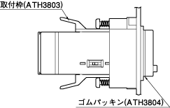
※取付枠とゴムパッキンにて取り付ける場合、あらかじめ装着しておりますOリングは取り外してください。
- パネル取付順序
- Oリングを取り外す。
- ゴムパッキンをはめる。
- 本体をパネルに挿入する。
- 取付枠を後部より入れる。
- 取付ネジで固定する(2ヶ所)
- 防水タイプ(IP66:パネル表面のみ)としてご使用の場合、アワーメータ本体を取付枠(ATH3803:別売り)とゴムパッキン(ATH3804:別売り)にて盤面に取り付け、取付補強ネジを必ず締め付けてご使用ください。
下記の環境では使用しないでください。
- 温度変化の激しい場所。
- 湿度が高く結露が生じる恐れのある場所。
(結露すると表示が消え、表示異常となる場合があります。)
使用条件について
- 引火性ガス、腐食性ガスの発生するところや、塵埃の多いところ、油のかかるところ、振動、衝撃の激しいところでのご使用は避けてください。
- 本体カバーはポリカーボネート樹脂製ですから、メチルアルコール、ベンジン、シンナーなどの有機溶剤や、アンモニア、苛性ソーダなど、強アルカリ性物質の付着やそれらの雰囲気でのご使用は避けてください。
電池交換時のご注意(LH2Hアワーメータ)※電池交換時リセットされます。
- 電池交換時は配線を外してください。高電圧が印加された箇所に触れると感電するおそれがあります。
- 電池交換時は身体に静電気が帯電していない状態で行ってください。
- 電池交換手順
LH2Hアワーメータ(ワンタッチ取付方式)
- 工具を用いてケースの「上下」フックを外してください。
- ケースから本体を引き出してください。
- 電池を本体側面より外してください。この時、表示部や部品に触れないでください。
- 電池を挿入する前に、電池の表面をきれいに拭いてください。
- 電池のプラス+、マイナス-を正しく入れてください。
- 電池交換後、本体をケースに戻します。このケースのフックが正しくかかっていることを確認してください。
- 使用前に前面のリセットボタンを押してください。(表示は全てリセットされます)
LH2Hアワーメータ(取付枠取付方式)
- ケースより電池フタ(1)を外してください。
- 電池(2)をケース側面より外してください。このとき本体側面(電池側)を下にして軽く振ると電池が外れます。
- 電池を挿入する前に、電池の表面をきれいに拭いてください。
- 電池のプラス+、マイナス-を正しく入れてください。
- 電池交換後、電池フタ(5)をケースに戻します。このとき電池フタのフックが正しくかかっていることを確認してください。
- 使用前に前面のリセットボタン(6)を押してください。
