Discontinued Products
Dimensions
- Unit: mm in
Dimensions
General tolerance : ±1.0 ±0.39
When installing the one-touch installation type model, make sure that the installation spring does not pinch the rubber gasket.
To prevent the installation spring from pinching the rubber gasket:
1.Set the rubber gasket on both ends of the installation spring (left and right).
2.Confirm that the installation spring is not pinching the rubber gasket, and then insert and fix the installation spring in place from the rear of the timer unit.
Panel cut out dimensions
The standard panel cut out is shown below. Use the mounting bracket (ATH3803) and the rubber gasket (ATH3804).
(Only installation frame type)
When installing repeatedly (sealed installation)
(Only installation frame type)
1* Suitable installation panel thickness is 1 to 4.5 mm/ 0.39 to 0.177 inch.2* Waterproofing will be lost when installing repeatedly (sealed installation).
Cautions For Use
Protective circuit for timer contact
In the circuit that switches an inductive load, a contact failure may occur at a contact point due to surge or inrush current resulting from that switching. Therefore, it is recommended that the following protective circuit be used to protect the contact point.
| CR circuit (r: resistor c: capacitor) | |||
|---|---|---|---|
| Circuit |
|
| |
| Application | AC | * Note: | Available |
| DC | Available | Available | |
| Features/Others | If the load is a relay or solenoid, the release time lengthens. Effective when connected to both contacts if the power supply voltage is 24 or 48 V and the voltage across the load is 100 to 200 V. | ||
| If the load is a timer, leakage current flows through the CR circuit causing faulty operation. Note: If used with AC voltage, be sure the impedance of the load is sufficiently smaller than that of the CR circuit. | - | ||
| Device Selection | As a guide in selecting r and c, c: 0.5 to 1 µF per 1 A contact current r: 0.5 to 1 ohm per 1 V contact voltage Values vary depending on the properties of the load and variations in timer characteristics. Capacitor c acts to suppress the discharge the moment the contacts open. Resistor r acts to limit the current when the power is turned on the next time. Test to confirm. Use a capacitor with a breakdown voltage of 200 to 300 V. Use AC type capacitors (non-polarized) for AC circuits. | ||
| Diode circuit | Varistor circuit | ||
|---|---|---|---|
| Circuit |
|
| |
| Application | AC | Not Available | Available |
| DC | Available | Available | |
| Features/Others | The diode connected in parallel causes the energy stored in the coil to flow to the coil in the form of current and dissipates it as joule heat at the resistance component of the inductive load. This circuit further delays the release time compared to the CR circuit. (2 to 5 times the release time listed in the catalog) | Using the rated voltage characteristics of the varistor, this circuit prevents excessively high voltages from being applied across the contacts. This circuit also slightly delays the release time. Effective when connected to both contacts if the power supply voltage is 24 or 48 V and the voltage across the load is 100 to 200 V. | |
| Device Selection | Use a diode with a reverse breakdown voltage at least 10 times the circuit voltage and a forward current at least as large as the load current. In electronic circuits where the circuit voltages reverse breakdown voltage of about 2 to 3 times the power supply voltage. | - | |
Type of Load and Inrush Current
The type of load and its inrush current characteristics, together with the switching frequency are important factors which cause contact welding. Particularly for loads with inrush currents, measure the steady state current and inrush current and use a relay or magnet switch which provides an ample margin of safety. The table below shows the relationship between typical loads and their inrush currents.
| Type of load | Inrush current |
|---|---|
| Resistive load | Steady state current |
| Solenoid load | 10 to 20 times the steady state current |
| Motor load | 5 to 10 times the steady state current |
| Incandescent lamp load | 10 to 15 times the steady state current |
| Mercury lamp load | 1 to 3 times the steady state current |
| Sodium vapor lamp load | 1 to 3 times the steady state current |
| Capacitive load | 20 to 40 times the steady state current |
| Transformer load | 5 to 15 times the steady state current |
When you want large load and long life of the counter, do not control the load direct with a timer. When the timer is designed to use a relay or a magnet switch, you can acquire the longer life of the counter.
Connection of input (Except for LC4H-S/AC type)
Since LC4H series counters use a transformerless power supply system, the input equipments must have the power supply transformer in which the secondary side is not grounded with the primary and secondary sides insulated, in order to prevent interference of the power supply circuit when connecting the external input circuit as Fig. A.
Be sure not to use an autotransformer. In case of secondary side grounded or using the autotransformer, this product may be destroyed due to short circuit electrically as Fig. B (1 and 2).
In case of F.G. terminal of equipments such a PLC grounded in secondary side of the transformer, inner circuits of this product and the input equipment may be destroyed due to short circuit electrically as Fig.B (3).
Therefore, use the isolated type counters or do not ground F.G. terminal of the products.
Long Continuous Current Flow
Avoid keeping the counter on for a long period of time (over one month). Otherwise heat is generated and accumulated inside the counter, which may deteriorate its electronic parts. If the counter must be kept on for a long period of time, a relay is added. See the circuit diagram below.
Leakage current
- 1.For connecting and disconnecting operating voltage to the counter, a circuit should be used, which will prevent the flow of leakage current. For example, a circuit for contact protection as shown in Fig A. will permit leakage current flow through R and C, causing erroneous operation of the counter. Instead, the circuit shown in Fig. B should be used.
- 2.If the counter is directly switched with a non-contact element, leak current may flow into the counter and cause it to malfunction.
Pin connections
Correctly connect the pins while seeing the pin layout/connection diagram. In particular, the DC type, which has polarities, does not operate with the polarities connected reverse. Any incorrect connection can cause abnormal heating or ignition.
Connection to operation power supply
- 1.Apply the entire supply voltage through a switch, relay or other contact.
- 2.The operation voltage for the DC type must be at the specified ripple percentage or less. The average voltage must fall within the allowable operation voltage range.
| Rectification type | Ripple percentage |
|---|---|
| Single-phase, full-wave | Approx. 48% |
| Three-phase, full-wave | Approx. 4% |
| Three-phase, half-wave | Approx. 17% |
- 3.Make sure that no induced voltage and residual voltage are applied between the power pins on the timer after the power switch is turned OFF.
(If the power line is wired in parallel with the high-voltage and motor lines, induced voltage may be produced between the power pins.)
Control output
- 1.Keep the load capacity below the counter's rated control capacity. If used above the rating, the counter's service life may shorten. With the transistor output type counters, transistors may be damaged.
Installing the counter
- 1.To install the counter, use the dedicated pin bracket or socket (cap). Avoid connecting the pins on the counter by directly soldering them.
- 2.In order to maintain the characteristics, do not remove the counter cover (case).
Superimposed surge of power supply
For the superimposed surge of power supply, the standard waveform (±1.2×50μs or ±1×40μs) is taken as the standard value for surge-proof voltage.
(The positive and negative voltages are applied each three or five times between the power pins.) For the standard values for the LC4H type counters, see the respective items in "Caution on usage."
If external surge occurs exceeding the specified value, the internal circuit may break down. In this case, use a surge absorption element. The typical surge absorption elements include a varistor, a capacitor, and a diode. If a surge absorption element is used, use an oscilloscope to see whether or not the foreign surge exceeding the specified value appears.
Signal input
The counter's signal input comes in two ways. One is by opening and closing the input terminal. The other is by applying a specified H-level or L-level voltage to the input terminal.
For an input sensor's residual voltage, input impedance, input voltage level and other signal input conditions, see the ratings for each type of product.
Operating environment
- 1.For the ambient operating temperature and humidity, see the ratings for each type of product.
- 2.Avoid using the counter in a location where (a) inflammable or corrosive gas is generated, (b) the counter is exposed to much dust and other foreign matter; (c) water or oil is splashed on the counter; or (d) vibrations or shocks are given to the counter.
- 3.The counter cover (case), the knobs, and the dials are made of polycarbonated resin. Therefore, prevent the counter from being exposed to organic solvents such as methyl alcohol, benzine, and thinner, strong acid substances such as caustic soda, and ammonia and avoid using the counter in atmosphere containing any of those substances.
- 4.If the counter is used where noises are emitted frequently, separate the input signal elements (such as a sensor), the wiring for the input signal line, and the counter as far as possible from the noise source and the high power line containing noises.
Checking the actual load
In order to increase the reliability in the actual use, check the quality of the counter in the actual usage.
Others
- 1. If the counter is used exceeding the ratings (operation voltage and control capacity), the contact life, or any other specified limit, abnormal heat, smoke, or ignition may occur.
- 2.The LC2H series counter, which provides a power failure compensation capability, incorporates a lithium battery.
Never disassemble the lithium battery or throw it into fire because this may affect humans and facilities. The lithium battery must be disposed of as an incombustible like other used batteries. - 3.If any malfunction of the counter is likely to affect human life and properties, give allowance to the rated values and performance values. In addition, take appropriate safety measures such as a duplex circuit from the viewpoint of product liabilities.
LC2H Preset Counter
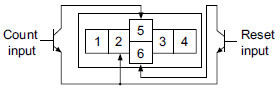
Input and output connection
1.Input connection
- 1.Contact input
- 2.Non-contact input (Transistor input)
- 3.Input wiring
Use highly reliable metal plated contacts. Since the contact's bounce time leads directly to error in the count value, use contacts with as short a bounce time as possible. In general, select input to have a maximum counting speed of 30 Hz.
Connect with an open collector. Use transistors whose characteristics satisfy the criteria given below.
VCEO = Min. 20 V
IC = Min. 20 mA
ICBO = Max. 6 μA
Also, use transistors with a residual voltage of less than 2 V when the transistor is on.
* The short-circuit impedance should be less than 1 kΩ.
(When the impedance is 0 Ω, the current coming from the count input terminal is approximately 5 mA and from the reset input terminal is approximately 1.5 mA.) Also, the open-circuit impedance should be more than 100 kΩ.
When wiring, use shielded wires or metallic wire tubes, and keep the wire lengths as short as possible.
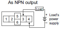
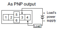
2.Output connection
Since the transistor output of counter is insulated from the internal circuitry by a photo-coupler, it can be used as an NPN output or PNP (equal value) output.
Self-diagnosis function
If a malfunction occurs, one of the following displays will appear.
| Display | Contents | Output condition | Restoration procedure | Preset values after restoration |
|---|---|---|---|---|
| Err-00 | Malfunctioning CPU | OFF | Enter front reset key or restart counter | The preset value at start-up before the CPU malfunction occurred. |
| Err-01 | Malfunctioning memory* | 0 |
*Includes the possibility that the EEP-ROM's life has expired.
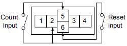
Terminal connection
1.When wiring the terminals, refer to the terminal layout and wiring diagrams and be sure to perform the wiring properly without errors.
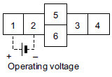
An external power supply is required in order to run the main unit.
- Power should be applied between terminals (1) and (2).
- Terminal (1) acts as the positive"+"connection and terminal (2) as the negative "–".
2.After turning the counter off, make sure that any resulting induced voltage or residual voltage is not applied to power supply terminals (1) through (2). (If the power supply wire is wired parallel to the high voltage wire or power wire, an induced voltage may be generated at the power supply terminal.)
3.Have the power supply voltage pass through a switch or relay so that it is applied at one time.
Changing The Preset Value
1.It is possible to change the preset value even during counting. However, be aware of the following points.
- 1.If the preset value is changed to less than the count value with counting set to the addition direction, counting will continue until it reaches full scale, returns to zero, and then reaches the new preset value. If the preset value is changed to a value above the count value, counting will continue until the count value reaches the new preset value.
- 2.Suppose that the counter is preset to count down. Whether a preset count down value is smaller or larger than the count value, the counter counts down to "0 (zero)".
2.If the preset value is changed to "0", the counter will not complete countup. It starts counting up when the counting value comes to "0 (zero)" again.
- 1.Addition (up-count) input when counting is set to the addition direction, counting will continue until full scale is reached, return to zero, and then complete count-up.
- 2.Subtraction (down-count) input when counting is set to the subtraction direction, counting will continue until full scale "--9999999" is reached, and then the display will change to [- - - - - - - -].
Precautions in Using The LC2H Series
Insulation sheet
Before using a panel mounting type, please pull and remove the insulation sheet from the side of the product in the direction of the arrow. In consideration that the product might be stored for long periods without being used, an insulation sheet is inserted before shipping. Remove the insulation sheet and press the front reset button.
LC2H total counter (one-touch installation type)
Waterproof construction
LC2H total counter (installation frame type)
The operation part of the panel installation type (installation frame type) is constructed to prevent water from entering the unit and a rubber gasket is provided to prevent water from entering the gap between the unit and the panel cutout. There must be sufficient pressure applied to the rubber gasket to prevent water from entering. Be sure to use the mounting reinforcement screws when installing the mounting frame (ATH3803).
Note:
The one-touch installation type is not waterproof.
LC2H preset counter
- 1.The front plate will not be waterproof when this product is installed on a panel.
To make the front plate waterproof, please install the following. When using the waterproof type (IP66: panel front only), install the counter to the front plate with mounting frame ATH3803 (sold separately) and rubber gasket ATH3804 (sold separately). Be sure to tighten using mounting screws.
When installing the mounting frame and rubber gasket please remove the pre-attached o-ring
- 2.Panel installation order
- 1.Remove o-ring.
- 2.Place rubber gasket.
- 3.Insert counter into panel.
- 4.Insert mounting frame from the rear.
- 5.Secure with mounting screws (two locations)
Do not use in the following environments
- 1.In places where the temperature changes drastically.
- 2.In places where humidity is high and there is the possibility of dew.
(When dew forms the display may vanish and other display errors may occur.)
Conditions of use
- 1.Do not use on places where there is flammable or corrosive gas, lots of dust, presence of oil, or where the unit might be subject to strong vibrations or shocks.
- 2.Since the cover is made of polycarbonate resin, do not use in places where the unit might come into contact with or be exposed to environments that contain organic solvents such as methyl alcohol, benzene and thinner, or strong alkali substances such as ammonia and caustic soda.
Cautions regarding battery replacement
- 1.Remove wiring before replacing the battery. You may be electrocuted if you come into contact to a part where high voltage is applied.
- 2.Make sure you are not carrying a static electric charge when replacing the battery.
- 3.Battery replacement procedure
1.For LC2H total counter (one-touch installation type)
- 1.Remove the up/down hook of the case using a tool.
- 2.Pull the unit away from the case.
- 3.Remove the battery from the side of the unit. Do not touch the display or other parts.
- 4.Before inserting wipe clean the surface of the new battery.
- 5.Insert the new battery with the "+" and "–" sides in the proper position.
- 6.After replacing the battery, return the unit to the case. Verify that the hook of the case has properly engaged.
- 7.Before using, press the reset button on the front.
2.For LC2H total counter (installation frame type)
- 1.Remove the battery cover from the case.
- 2.Remove the battery from the side of the case. The battery will come loose if you put the battery side face down and lightly shake the unit.
- 3.Before inserting wipe clean the surface of the new battery.
- 4.Insert the new battery with the "+" and "–" sides in the proper position.
- 5.After replacing the battery, return the battery cover to the case. Verify that the hook of the battery cover is properly engaged.
- 6.Before using press the reset button on the front.
Terminal connection
Tighten the terminal screws with a torque of 0.8 N·cm or less.