Discontinued Products
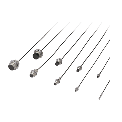
Dimensions
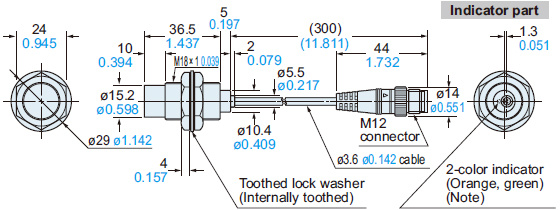
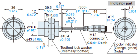
Unit: mm in
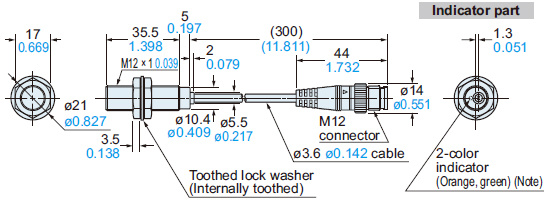
GX-5SU
GX-5SUB
Sensor
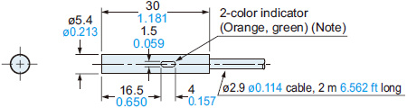
Note:GX-5SUB has an operation indicator (orange) instead of the 2-color indicator.
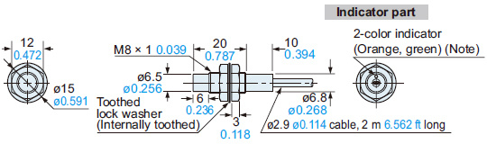
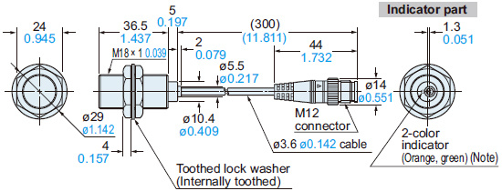
GX-8MU
GX-8MUB
Sensor
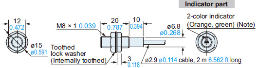
Note:GX-8MUB has an operation indicator (orange) instead of the 2-color indicator.
GX-12MU(B)
GX-N12M(B)
Sensor

Note:GX-12MUB and GX-N12M(B) have an operation indicator (orange) instead of the 2-color indicator.
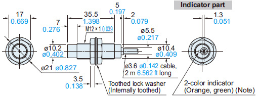
GX-18MU(B)
GX-N18M(B)
Sensor
Note:GX-18MUB and GX-N18M(B) have an operation indicator (orange) instead of the 2-color indicator.
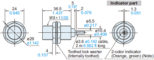
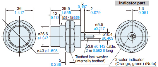
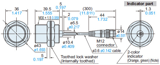
GX-30MU(B)
GX-N30M(B)
Sensor
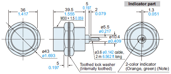
Note:GX-30MUB and GX-N30M(B) have an operation indicator (orange) instead of the 2-color indicator.
GX-8MLU
GX-8MLUB
Sensor
Note:GX-8MLUB has an operation indicator (orange) instead of the 2-color indicator.
GX-12MLU(B)
GX-N12ML(B)
Sensor
Note:GX-12MLUB and GX-N12ML(B) have an operation indicator (orange) instead of the 2-color indicator.
GX-18MLU(B)
GX-N18ML(B)
Sensor

Note:GX-18MLUB and GX-N18ML(B) have an operation indicator (orange) instead of the 2-color indicator.
GX-30MLU(B)
GX-N30ML(B)
Sensor
Note:GX-30MLUB and GX-N30ML(B) have an operation indicator (orange) instead of the 2-color indicator.
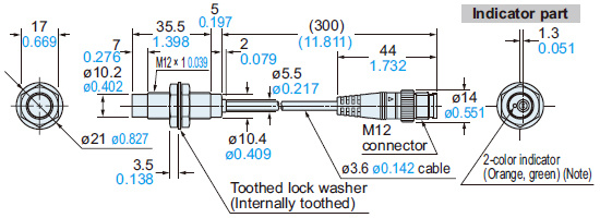
GX-12MU(B)-J
GX-F12MU-J
Sensor
Note:GX-12MUB-J has an operation indicator (orange) instead of the 2-color indicator.
GX-18MU(B)-J
GX-F18MU-J
Sensor
Note:GX-18MUB-J has an operation indicator (orange) instead of the 2-color indicator.
GX-30MU(B)-J
GX-F30MU-J
Sensor
Note:GX-30MUB-J has an operation indicator (orange) instead of the 2-color indicator.
GX-12MLU-J
GX-12MLUB-J
Sensor
Note:GX-12MLUB-J has an operation indicator (orange) instead of the 2-color indicator.
GX-18MLU-J
GX-18MLSB-J
Sensor
Note:GX-18MLUB-J has an operation indicator (orange) instead of the 2-color indicator.
GX-30MLU-J
GX-30MLUB-J
Sensor
Note:GX-30MLUB-J has an operation indicator (orange) instead of the 2-color indicator.
MS-SS5
Sensor mounting bracket for GX-5SU(B) (Optional)
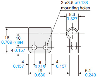
Material:Nylon 66
MS-H12 MS-H18 MS-H30
Protection cover (Optional)
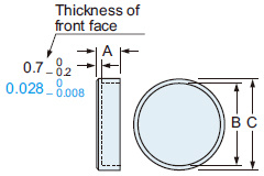
Material:Fluorine resin
| Model No. | A | B | C | Applicable model No. |
|---|---|---|---|---|
| MS-H12 | 5 | ø11.5 ø0.453 | ø14 ø0.551 | GX-12MU(B) GX-N12M(B) |
| MS-H18 | 6 | ø17.5 ø0.689 | ø20 ø0.787 | GX-18MU(B) GX-N18M(B) |
| MS-H30 | 8 | ø29.4 ø1.157 | ø33 ø1.299 | GX-30MU(B) GX-N30M(B) |
I/O Circuit and Wiring diagrams
GX-□U(B)
DC 2-wire type
I/O circuit diagram
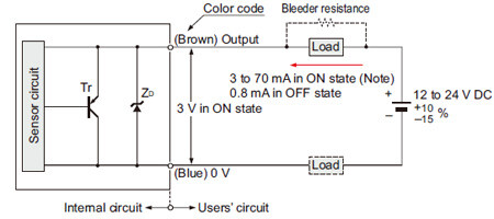
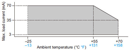
Note: The maximum load current varies depending on the ambient temperature.
Symbols・・・
ZD: Surge absorption zener diode
Tr : PNP output transistor
Wiring diagram

Conditions for the load
(1)The load should not be actuated by the leakage current (0.8 mA) in the OFF state.
(2)The load should be actuated by (supply voltage – 3 V) in the ON state.
(3)The current in the ON state should be between 3 to 70 mA DC.
[In case the current is less than 3 mA, connect a bleeder resistance in parallel to the load so that a current of 3 mA, or more, flows.]
GX-□U(B)-J GX-F□U-J
Spatter-resistant of DC 2-wire type
I/O circuit diagram

Notes:
1) This is when the mating cable CN-22G-C□ is connected. The connecter pins No.2 and No.4 are short-circuited inside the mating cable connecter. However, when the mating cable CN-24-C□ is connected;
GX-□U-J (normally open): (Black / 4) 0 V
GX-□UB-J (normally closed): (White / 2) 0 V
2) The maximum load current varies depending on the ambient temperature.

Conditions for the load
1) The load should not be actuated by the leakage current (0.8 mA) in the OFF state.
2) The load should be actuated by (supply voltage – 3 V) in the ON state.
3) The current in the ON state should be between 3 to 70 mA DC.
[In case the current is less than 3 mA, connect a bleeder resistance in parallel to the load so that a current of 3 mA, or more, flows.]
Symbols・・・
ZD: Surge absorption zener diode
Tr : PNP output transistor
Wiring diagram

Note: This is when the mating cable CN-22G-C□ is connected. The connecter pins No.2 and No.4 are short-circuited inside the mating cable connecter.
However, when the mating cable CN-24-C□ is connected;
GX-□U-J (normally open): Black / 4
GX-□UB-J (normally closed): White / 2
Connector pin position
GX-□U-J (Normally open)

GX-□UB-J (Normally closed)

GX-F□U-J (Spatter-resistant type)

GX-N□
DC 3-wire type (NPN output)
I/O circuit diagram

Note: If a capacitive load is directly connected to the output, malfunction may occur.
Symbols・・・
D : Reverse supply polarity protection diode
ZD: Surge absorption zener diode
Tr: NPN output transistor
Wiring diagram


As the sensing object size becomes smaller than the standard size (iron sheet 6 × 6 × t 1 mm 0.236 × 0.236 × t 0.039 in), the sensing range shortens as shown in the left figure.


As the sensing object size becomes smaller than the standard size (iron sheet 8 × 8 × t 1 mm 0.315 × 0.315 × t 0.039 in), the sensing range shortens as shown in the left figure.


As the sensing object size becomes smaller than the standard size (iron sheet 12 × 12 × t 1 mm 0.472 × 0.472 × t 0.039 in), the sensing range shortens as shown in the left figure.


As the sensing object size becomes smaller than the standard size (iron sheet 18 × 18 × t 1 mm 0.709 × 0.709 × t 0.039 in), the sensing range shortens as shown in the left figure.


As the sensing object size becomes smaller than the standard size (iron sheet 30 × 30 × t 1 mm 1.181 × 1.181 × t 0.039 in), the sensing range shortens as shown in the left figure.


As the sensing object size becomes smaller than the standard size (iron sheet 20 × 20 × t 1 mm 0.787 × 0.787 × t 0.039 in), the sensing range shortens as shown in the left figure.


As the sensing object size becomes smaller than the standard size (iron sheet 30 × 30 × t 1 mm 1.181 × 1.181 × t 0.039 in), the sensing range shortens as shown in the left figure.


As the sensing object size becomes smaller than the standard size (iron sheet 50 × 50 × t 1 mm 1.969 × 1.969 × t 0.039 in), the sensing range shortens as shown in the left figure.


As the sensing object size becomes smaller than the standard size (iron sheet 70 × 70 × t 1 mm 2.756 × 2.756 × t 0.039 in), the sensing range shortens as shown in the left figure.


As the sensing object size becomes smaller than the standard size (iron sheet 12 × 12 × t 1 mm 0.472 × 0.472 × t 0.039 in), the sensing range shortens as shown in the left figure.


As the sensing object size becomes smaller than the standard size (iron sheet 18 × 18 × t 1 mm 0.709 × 0.709 × t 0.039 in), the sensing range shortens as shown in the left figure.


As the sensing object size becomes smaller than the standard size (iron sheet 30 × 30 × t 1 mm 1.181 × 1.181 × t 0.039 in), the sensing range shortens as shown in the left figure.


As the sensing object size becomes smaller than the standard size (iron sheet 30 × 30 × t 1mm 1.181 × 1.181 × t 0.039 in), the sensing range shortens as shown in the left figure.


As the sensing object size becomes smaller than the standard size (iron sheet 50 × 50 × t 1 mm 1.969 × 1.969 × t 0.039 in), the sensing range shortens as shown in the left figure.


As the sensing object size becomes smaller than the standard size (iron sheet 70 × 70 × t 1 mm 2.756 × 2.756 × t 0.039 in), the sensing range shortens as shown in the left figure.
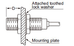
<Non-threaded type>

Mounting hole process dimension
![]()
| Model No. | A (mm in) | B (mm in) | C (mm in) | Tightening torque |
|---|---|---|---|---|
| GX-5SU(B) | 5 to 30 0.197 to 1.181 | 3 0.118 | ø5.5+ 0.20ø0.217+ 0.0080 | 0.29 N·m (Note) |
Note : From the shipment on October, 2019.
- Do not fix on the operation indicator and opposite to it.
![シリンダ型近接センサ[アンプ内蔵] GX-U/GX-FU/GX-N](https://ap.industry.panasonic.com/hubfs/pid-corp/products/fasys/sensor/proximity/gx-u_gx-n/attention/images/pic03.jpg)
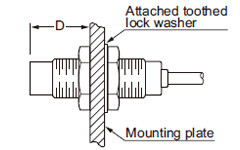
Mounting with nut
<Shielded of threaded type>
<Non-shielded of threaded type>


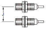
Face to face mounting
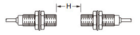
Parallel mounting

Others
- Do not use during the initial transient time (50 ms) after the power supply is switched on.
- Make sure that stress by forcible bend or pulling is not applied directly to the sensor cable joint.
<DC 2-wire type>
Wiring
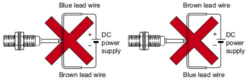
- The sensor must be connected to a power supply via a load. If the sensor is connected to a power supply without a load, the short-circuit protection makes the sensor inoperable. (The output stays in the OFF state and the indicator does not light up.) In this case, rectify by connecting the power supply via a load. Now, the sensor becomes operable. Further, take care that if the power supply is connected with reverse polarity without a load, the sensor will get damaged.
- For series connection (AND circuit) or parallel connection (OR circuit) of sensors, take care of the following.
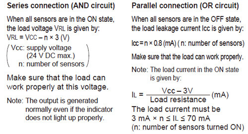

- The residual voltage of the sensor is 3 V. Before connecting a relay as the load, take care of its actuation voltage.
(Some 12 V relays may not be usable.)
2-color indicator [GX-(F)□U(-J) only]
- When the sensing object is in the stable sensing range, the LED lights up in green, and when the sensing object is in the unstable sensing range, the LED lights up in orange. While the LED lights up in green, the sensing is performed stably without being affected by temperature drifts or voltage fluctuations.
