Discontinued Products
Specifications
| Type | Small | ||
|---|---|---|---|
| With cable | With connector | ||
| Model No. | NPN output | PM-□44 | PM-□54 |
| PNP output | PM-□44P | PM-□54P | |
| Sensing range | 5 mm 0.197 in (fixed) | ||
| Minimum sensing object | 0.8 x 1.8 mm 0.031 x 0.071 in opaque object | ||
| Hysteresis | 0.05 mm 0.002 in or less | ||
| Repeatability | 0.03 mm 0.001 in or less | ||
| Supply voltage | 5 to 24 V DC ±10 % Ripple P-P 10 % or less | ||
| Current consumption | 15 mA or less | ||
| Output | <NPN output type> NPN open-collector transistor • Maximum sink current: 50 mA • Applied voltage: 30 V DC or less (between output and 0 V) • Residual voltage: 0.7 V or less (at 50 mA sink current), 0.4 V or less (at 16 mA sink current) <PNP output type> PNP open-collector transistor • Maximum source current: 50 mA • Applied voltage: 30 V DC or less (between output and +V) • Residual voltage: 0.7 V or less (at 50 mA source current), 0.4 V or less (at 16 mA source current) | ||
| Utilization category | DC-12 or DC-13 | ||
| Output operation | Incorporated with 2 outputs: Light-ON / Dark-ON | ||
| Response time | Under light received condition: 20 µs or less, Under light interrupted condition: 100 µs or less (Response frequency: 1 kHz or more) (Note 2) | ||
| Operation indicator | Vermilion LED (lights up under light received condition) | ||
| Pollution degree | 3 (Industrial environment) | ||
| Ambient temperature | –25 to +55 ℃ -13 to +131 ℉ (No dew condensation or icing allowed), Storage: –30 to +80 ℃ –22 to +176 ℉ | ||
| Ambient humidity | 35 to 85 % RH, Storage: 35 to 85 % RH | ||
| Ambient illuminance | Fluorescent light: 1,000 ℓx at the light-receiving face | ||
| EMC | EN 60947-5-2 | ||
| Voltage withstandability | 1,000 V AC for one min. between all supply terminals connected together and enclosure | ||
| Insulation resistance | 50 MΩ, or more, with 250 V DC megger between all supply terminals connected together and enclosure | ||
| Vibration resistance | 10 to 2,000 Hz frequency, 1.5 mm 0.059 in amplitude in X, Y and Z directions for two hours each | ||
| Shock resistance | 15,000 m/s2 acceleration (1,500 G approx.) in X, Y and Z directions for three times each | ||
| Emitting element | Infrared LED (Peak emission wavelength: 940 nm 0.037 mil, non-modulated) | ||
| Material | Enclosure: PBT, Slit cover: Polycarbonate, Terminal part [PM-□54(P) only]: Solder plated | ||
| Cable | 0.09 mm2 4-core cabtyre cable, 1 m 3.281 ft long | - | |
| Cable extension | Extension up to total 100 m 328.084 ft is possible with 0.3 mm2, or more, cable. | ||
| Weight | Net weight: 15 g approx. | Net weight: 3 g approx. | |
Notes:
1) Where measurement conditions have not been specified precisely, the conditions used were an ambient temperature of +23 ℃ +73.4 ℉.
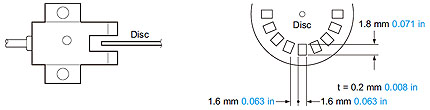
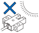
2) The response frequency is the value when the disc, given in the figure below, is rotated.
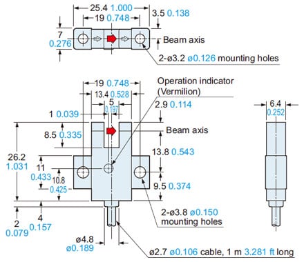
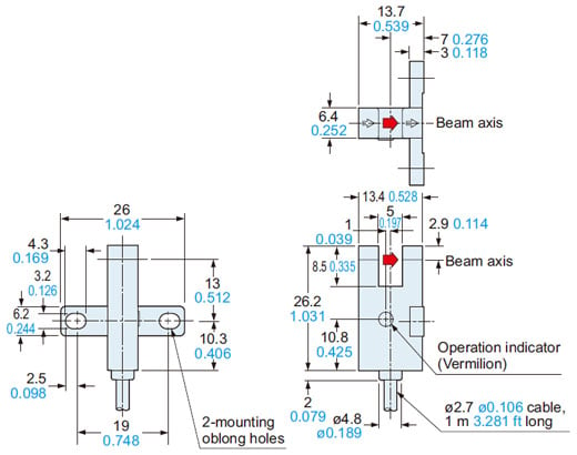
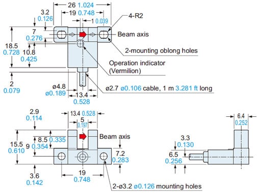
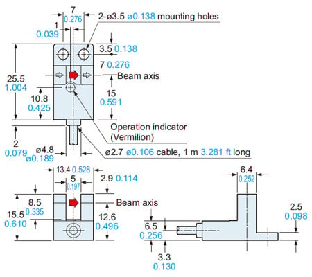
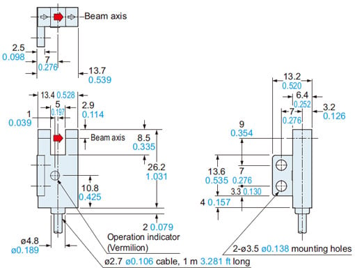
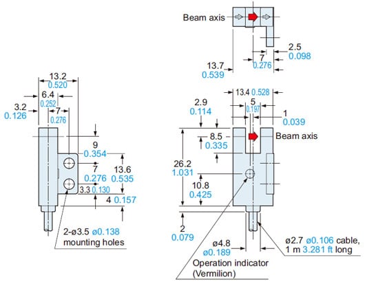
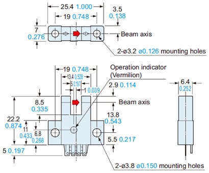
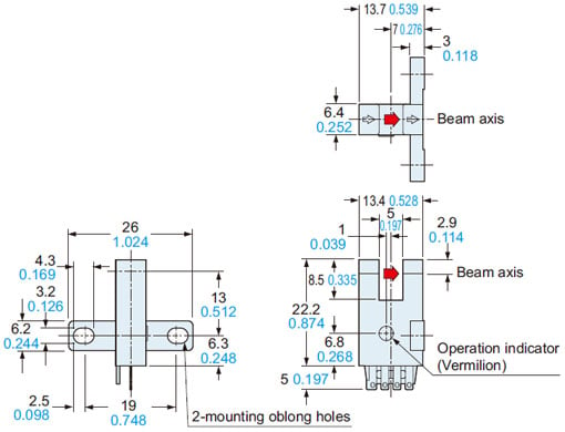
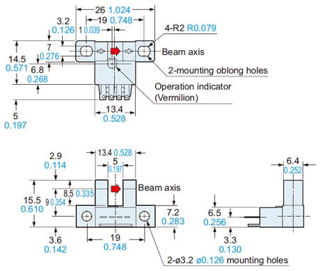
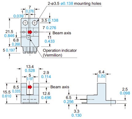
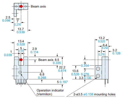
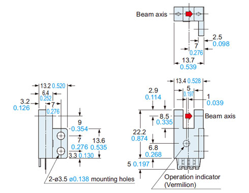
Dimensions
- Unit: mm in
PM-K44
PM-K44P
Sensor
PM-T44
PM-T44P
Sensor
PM-L44
PM-L44P
Sensor
PM-Y44
PM-Y44P
Sensor
PM-F44
PM-F44P
Sensor
PM-R44
PM-R44P
Sensor
PM-K54
PM-K54P
Sensor
PM-T54
PM-T54P
Sensor
PM-L54
PM-L54P
Sensor
PM-Y54
PM-Y54P
Sensor
PM-F54
PM-F54P
Sensor
PM-R54
PM-R54P
Sensor
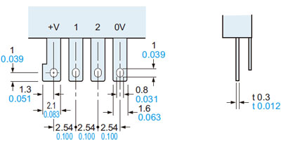
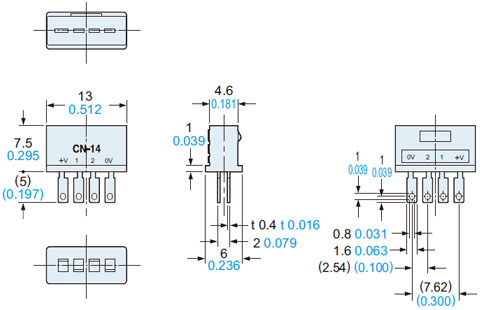
Terminal part (PM-□54, PM-□54P)
CN-14
Connector (Optional)
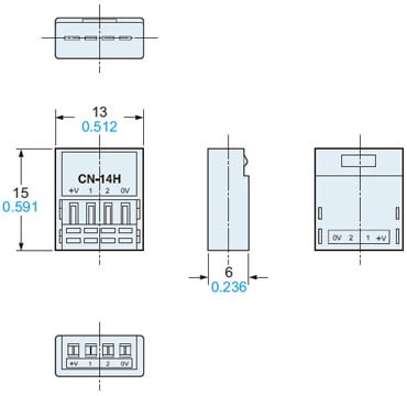
CN-14H
CN-14H-2
Hook-up connector (Optional)
CN-14H-C1
CN-14H-C3
Connector attached cable (Optional)
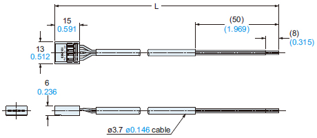
• Length L
| Model No. | Length L |
|---|---|
| CN-14H-C1 | 1 m 3.281 ft |
| CN-14H-C3 | 3 m 9.843 ft |
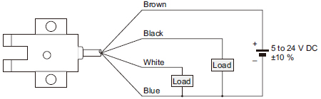
I/O Circuit and Wiring diagrams
PM-□44
PM-□54
NPN output type
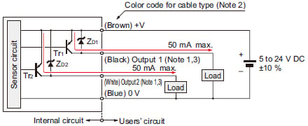
I/O circuit diagram
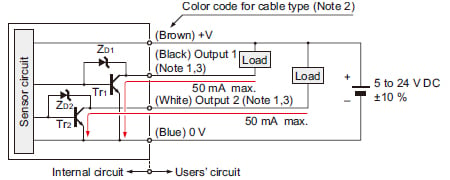
Notes:
1)Make sure to connect terminals correctly as the sensor does not incorporate a reverse polarity protection circuit.Further, the output is not incorporated with a short-circuit protection circuit. Do not connect it directly to a power supply or a capacitive load.Faulty wiring may result in damage.
2)The color code of the connector attached cable is also the same.
3)Ensure to insulate the unused output wire.
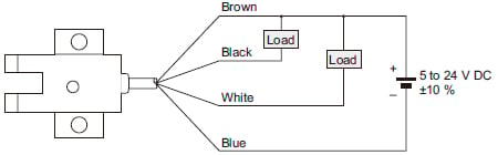
Wiring diagram
Output operation
| Color code | Output operation | |
|---|---|---|
| Output 1 | Black | Light-ON |
| Output 2 | White | Dark-ON |
PM-□44P
PM-□54P
PNP output type
I/O circuit diagram
Notes:1)Make sure to connect terminals correctly as the sensor does not incorporate a reverse polarity protection circuit.Further, the output is not incorporated with a short-circuit protection circuit. Do not connect it directly to a power supply or a capacitive load.Faulty wiring may result in damage.2)The color code of the connector attached cable is also the same.3)Ensure to insulate the unused output wire.
Wiring diagram
Output operation
| Color code | Output operation | |
|---|---|---|
| Output 1 | Black | Light-ON |
| Output 2 | White | Dark-ON |
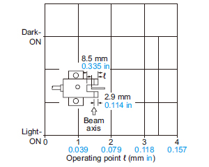
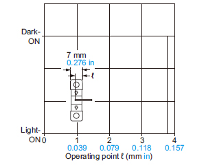
Sensing characteristics
(TYPICAL)
PM-L44(P)/K44(P)
PM-L54(P)/K54(P)
Sensing position
Mounting
- When fixing the sensor with screws, use M3 screws and the tightening torque should not exceed the values given below.
Further, use small, round type plain washers (ø6 mm ø0.236 in).
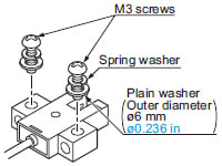
| Model No. | Tightening torque |
|---|---|
| PM-□44(P) | 0.5 N·m |
| PM-□54(P) |
Cable extension
- Cable extension is possible up to an overall length of 100 m 328.084 ft with a 0.3 mm2, or more, cable.
However, since a voltage drop shall occur due to the cable extension, ensure that the power supply voltage at the end of the cable attached to the sensor or at the sensor terminals is within the rating.
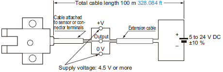
But, when the overall cable length, including the cable attached to the sensor, is as given below, there is no need to confirm the voltage.
| Conductor cross-section area of extension cable | Total cable length |
|---|---|
| 0.08 to 0.1 mm2 | Up to 5 m 16.404 ft |
| 0.2 mm2 | Up to 10 m 32.808 ft |
| 0.3 mm2 | Up to 20 m 65.617 ft |
Others
- Since the sensor is intended for use inside machines, no special countermeasures have been taken against extraneous light. Take care that extraneous light is not directly incident on the beam receiving section.
- Do not use during the initial transient time (50 ms) after the power supply is switched on.
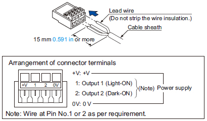
PM-□54 PM-□54P

(1) Strip the cable sheath 15 mm 0.591 in, or more, and insert the wires into the connector insertion holes till the wire tips reach the end.

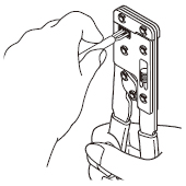
(2) When unplugging, give as much stress as a connector lug can be relieved from a hook. Then unplug it.

Caution: Be sure to hold a connector when plugging or unplugging it. Do not hold a terminal or a cable when plugging or unplugging the connector. Otherwise, it will cause a poor contact.
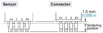
Soldering (Both connector CN-14 and sensor)
- If soldering is done directly on the terminals, strictly adhere to the conditions given below.
| Soldering temperature | 260 ℃ 500 ℉ or less |
|---|---|
| Soldering time | 3 sec. or less |
| Soldering position | Refer to the below figure |
Crimping of hook-up connectors CN-14H and CN-14H-2
| Item | CN-14H | CN-14H-2 |
|---|---|---|
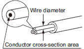
| Conductor cross-section area | 0.08 to 0.2 mm2 (AWG28 to AWG24) | 0.18 to 0.22 mm2 (AWG25 to AWG24) |
| Wire diameter | ø0.7 to ø1.2 mm ø0.028 to ø0.047 in | ø1.2 to ø1.52 mm ø0.047 to ø0.060 in |
| Wire insulation material | Vinyl chloride or soft polyethylene | |
Crimping method
(1) Strip the cable sheath 15 mm 0.591 in, or more, and insert the wires into the connector insertion holes till the wire tips reach the end.
(2) Crimp with the exclusive hook-up pliers CN-HP.
Notes:
1) When attaching or detaching the connector fitted with a cable, make sure to hold the connector firmly before proceeding.
2) After crimping, do not pull on the cable.
Caution:
Make sure to use the exclusive hook-up pliers CN-HP. Commercially available pliers cannot be used.
- Prior to using the sensor, affix the cable in a way as to avoid direct stress on the crimped part.