------------------------------ Tab1 showing ------------------------------
Basic Information
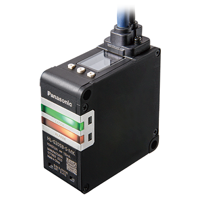
High-precision Displacement Sensors Made Easier to Use


UL, CSA : Certified by TÜV SÜD America Inc.
Features
Industry’s top-class*1 measuring performance
High-precision Measurement
The HL-G2 series boasts the industry’s top-class*1 performance such as resolution*2 of 0.5 μm 0.020 mil, linearity*2 of ±0.05 % F.S., sampling period of 100 μs (fastest) and temperature characteristic of 0.03 % F.S./°C. The HL-G2 sensors deliver the performance rivaling those of displacement meters of one class above, thanks to the optimized and balanced devices, optical system, mechanisms and algorithm. The organic EL display offers excellent visibility. The display language can be selected from English, Japanese and Chinese (simplified Chinese).
*1: According to our company’s survey, as of February 2024.
*2: Specifications vary depending on models.

Built-in controller and communication unit
Easy-to-use Integrated Models
The integrated models feature built-in controllers to facilitate model selection and reduce installation space and cost. The communication type models have built-in communication units for easy connection to a PLC, while the analog output type models are suitable for applications that require continuous acquisition of measurement data from sensors.
* Communication function is provided only in the communication type models.
* EtherNet/IP is a registered trademark of ODVA (Open DeviceNet Vendor Association).
* SLMP is a registered trademark of Mitsubishi Electric Corporation.
* Modbus is a registered trademark of Schnelder Electric USA Inc.

Simple and intuitive operation
Setting Tool Software: HL-G2 Configuration Tool
Basic setting operations such as change / writing of settings, monitoring of received light waveform, image output of measured data / graph and high-speed logging can be performed intuitively, so even people unfamiliar with those operations can enter settings easily. Since the sensor settings can be saved to the computer under a name, it is easy to recover the sensor settings if they are accidentally changed, or to expand the settings when adding sensors for the same application.

Setting Tool Software Can Be Operated Even During Equipment Operation*
Each sensor can be connected to multiple upper-level devices so that the setting tool software can be connected and set even during equipment operation. In the case RS-485 communication is used, there is no need to change the connecting cable.
*: When Ethernet communication cable is used
Five different measuring ranges and two different output types available
Output Type Product Lineup

Lineup of Measuring Ranges

------------------------------ Tab2 showing ------------------------------
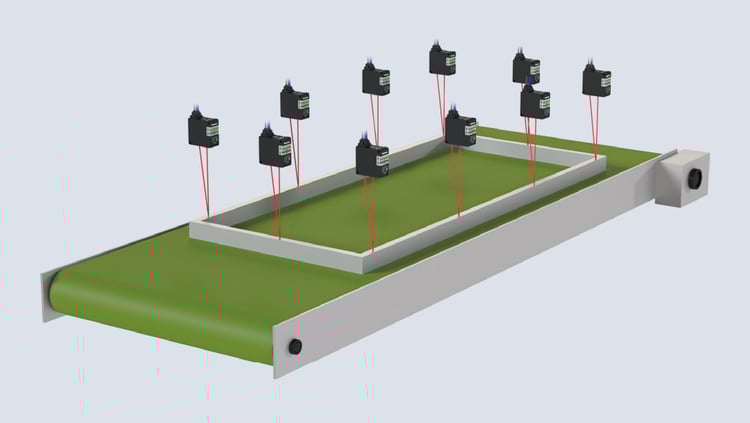
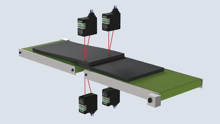
Inspection of automobile part shape

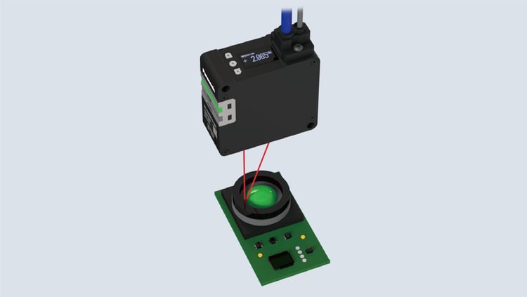
Inspection of camera actuator operating amount
Inspection of flatness of metal frame
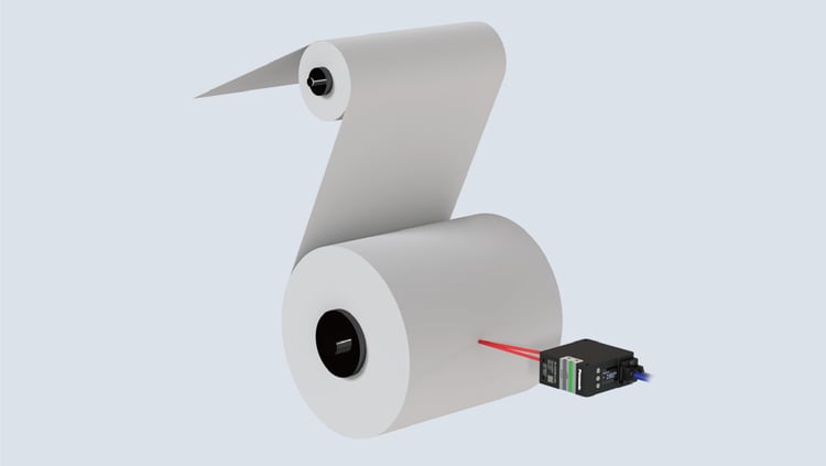
Confirmation of remaining roll amount
Control of dispenser height
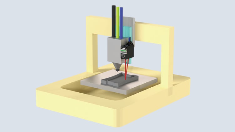
Detection of overlapping rubber parts
------------------------------ Tab3 showing ------------------------------
Order guide
Cables are not supplied with sensor units. Be sure to purchase optional cables.
| Type | Appearance | Measurement | Beam diameter (Note 2, 3) | Resolution | Linearity Limited range (top) Other (bottom) | Model No. |
|---|---|---|---|---|---|---|
| Communication type | 
| 30 mm±5 mm 1.181 in ±0.197 in | X-axis: 40 μm 1.575 mil approx. Y-axis: 1,000 μm 39.370 mil approx. | 0.5μm 0.020 mil | ±0.05%F.S. (27.5 mm to 32.5 mm) (1.083 in to 1.280 in) | HL-G203B-S-MK |
| ±0.075%F.S. | ||||||
| 50mm±10mm 1.969 in ±0.394 in | X-axis: 60 μm 2.362 mil approx. Y-axis: 2,000 μm 78.740 mil approx. | 1.5μm 0.059 mil | ±0.05%F.S. (45 mm to 55 mm) (1.772 in to 2.165 in) | HL-G205B-S-MK | ||
| ±0.075%F.S. | ||||||
| 85mm±20mm 3.346 in ±0.787 in | X-axis: 90 μm 3.543 mil approx. Y-axis: 3,000 μm 118.110 mil approx. | 2.5μm 0.098 mil | ±0.05%F.S. (75 mm to 95 mm) (2.953 in to 3.740 in) | HL-G208B-S-MK | ||
| ±0.075%F.S. | ||||||
| 120mm±30mm 4.724 in ±1.181 in | X-axis: 100 μm 3.937 mil approx. Y-axis: 4,000 μm 157.480 mil approx. | 4μm 0.157 mil | ±0.05%F.S. (105 mm to 135 mm) (4.134 in to 5.315 in) | HL-G212B-S-MK | ||
| ±0.075%F.S. | ||||||
| 250mm±150mm 9.843 in ±5.906 in | X-axis: 300 μm 11.811 mil approx. Y-axis: 8,000 μm 314.961 mil approx. | 15μm 0.591 mil | ±0.15%F.S. (200 mm to 300 mm) (7.874 in to 11.811 in) | HL-G225B-S-MK | ||
| ±0.25%F.S. | ||||||
| Analog output type | 30 mm±5 mm 1.181 in ±0.197 in | X-axis: 40 μm 1.575 mil approx. Y-axis: 1,000 μm 39.370 mil approx. | 0.5μm 0.020 mil | ±0.05%F.S. (27.5 mm to 32.5 mm) (1.083 in to 1.280 in) | HL-G203B-A-MK | |
| ±0.075%F.S. | ||||||
| 50mm±10mm 1.969 in ±0.394 in | X-axis: 60 μm 2.362 mil approx. Y-axis: 2,000 μm 78.740 mil approx. | 1.5μm 0.059 mil | ±0.05%F.S. (45 mm to 55 mm) (1.772 in to 2.165 in) | HL-G205B-A-MK | ||
| ±0.075%F.S. | ||||||
| 85mm±20mm 3.346 in ±0.787 in | X-axis: 90 μm 3.543 mil approx. Y-axis: 3,000 μm 118.110 mil approx. | 2.5μm 0.098 mil | ±0.05%F.S. (75 mm to 95 mm) (2.953 in to 3.740 in) | HL-G208B-A-MK | ||
| ±0.075%F.S. | ||||||
| 120mm±30mm 4.724 in ±1.181 in | X-axis: 100 μm 3.937 mil approx. Y-axis: 4,000 μm 157.480 mil approx. | 4μm 0.157 mil | ±0.05%F.S. (105 mm to 135 mm) (4.134 in to 5.315 in) | HL-G212B-A-MK | ||
| ±0.075%F.S. | ||||||
| 250mm±150mm 9.843 in ±5.906 in | X-axis: 300 μm 11.811 mil approx. Y-axis: 8,000 μm 314.961 mil approx. | 15μm 0.591 mil | ±0.15%F.S. (200 mm to 300 mm) (7.874 in to 11.811 in) | HL-G225B-A-MK | ||
| ±0.25%F.S. |
Notes :
1) Unless otherwise specified, the above specifications are typical values measured under the following measurement conditions. They do not guarantee performance for all target objects.
Power supply voltage: 24 V DC, ambient temperature: 20 ℃ 68 ℉, sampling cycle: 1 ms, average count: 512 times, measurement center distance, target object: visible light shielding ceramic
2) The X and Y axes of the beam diameter are specified as shown in the figure follow.
3) The beam diameter is defined as 1/e2 (approx. 13.5 %) of the center light intensity. Due to leak light outside the defined range, the measurement values may be affected if the reflectance around the detecting point is higher than that of the detecting point.
------------------------------ Tab4 showing ------------------------------
Option
Cables are not supplied with sensor units. Be sure to purchase optional cables.
| Type | Appearance | Model No. | Description | |||
|---|---|---|---|---|---|---|
| Optional cable | Ethernet type | 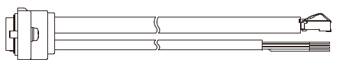 | CN-8E-C2 | Length 2 m 6.562 ft | Used with communication type sensor HL-G2□B-S-MK. Two M2.6 screws provided. | |
| CN-8E-C5 | Length 5 m 16.404 ft | |||||
| RS-485 type | 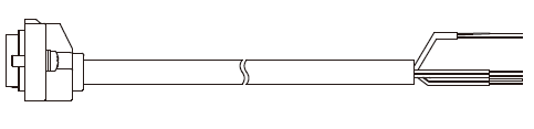 | CN-8R-C2 | Length 2 m 6.562 ft | |||
| CN-8R-C5 | Length 5 m 16.404 ft | |||||
| CN-8R-C10 | Length 10 m 32.808 ft | |||||
| CN-8R-C20 | Length 20 m 65.617 ft | |||||
| Analog output type | | CN-8A-C2 | Length 2 m 6.562 ft | Used with analog output type sensor HL-G2□B-A-MK. Two M2.6 screws provided. | ||
| CN-8A-C5 | Length 5 m 16.404 ft | |||||
------------------------------ Tab5 showing ------------------------------
Specifications
Communication type
| Item | Type | Communication type | |||||
|---|---|---|---|---|---|---|---|
| Model No. | HL-G203B-S-MK | HL-G205B-S-MK | HL-G208B-S-MK | HL-G212B-S-MK | HL-G225B-S-MK | ||
| Applicable regulations and certifications | CE Marking (EMC Directive, RoHS Directive), UKCA Marking (EMC Regulations, RoHS Regulations), FDA Regulation, TÜV SÜD Certification (U.S.A., Canada), Korea KC Mark | ||||||
| Measurement center distance | 30 mm 1.181 in | 50 mm 1.969 in | 85 mm 3.346 in | 120 mm 4.724 in | 250 mm 9.843 in | ||
| Measurement range | ±5 mm ±0.197 in | ±10 mm ±0.394 in | ±20 mm ±0.787 in | ±30 mm ±1.181 in | ±150 mm ±5.906 in | ||
| Beam diameter (Note 2)(Note 3) | X-axis: 40 μm 1.575 mil approx. Y-axis: 1,000 μm 39.370 mil approx. | X-axis: 60 μm 2.362 mil approx. Y-axis: 2,000 μm 78.740 mil approx. | X-axis: 90 μm 3.543 mil approx. Y-axis: 3,000 μm 118.110 mil approx. | X-axis: 100 μm 3.937 mil approx. Y-axis: 4,000 μm 157.480 mil approx. | X-axis: 300 μm 11.811 mil approx. Y-axis: 8,000 μm 314.961 mil approx. | ||
| Resolution | 0.5 μm 0.020 mil | 1.5 μm 0.059 mil | 2.5 μm 0.098 mil | 4 μm 0.157 mil | 15 μm 0.591 mil | ||
| Linearity | Limited range | ±0.05%F.S. (27.5 mm to 32.5 mm) (1.083 in to 1.280 in) | ±0.05%F.S. (45 mm to 55 mm) (1.772 in to 2.165 in) | ±0.05%F.S. (75 mm to 95 mm) (2.953 in to 3.740 in) | ±0.05%F.S. (105 mm to 135 mm) (4.134 in to 5.315 in) | ±0.15%F.S. (200 mm to 300 mm) (7.874 in to 11.811 in) | |
| Other than above | ±0.075%F.S. | ±0.075%F.S. | ±0.075%F.S. | ±0.075%F.S. | ±0.25%F.S. | ||
| Temperature characteristics | 0.03 %F.S./℃ | ||||||
| Measuring method | Diffuse reflection | ||||||
| Light source | Red semiconductor laser: Class 2 [IEC / EN / JIS / GB / KS / FDA Laser Notice No. 56 (Note 4)] Maximum output: 1 mW, Peak emission wavelength: 655 nm | ||||||
| Light receiving element | CMOS image sensor | ||||||
| Power supply voltage | Power supply units with a current capacity of 500 mA or more, including 24 V DC ±10 %, ripple 0.5 V (P-P) | ||||||
| Current consumption | 150 mA or less (Note 5) | ||||||
| Sampling cycle | 100 μs, 200 μs, 500 μs, 1 ms, 2 ms | ||||||
| Communication interface | Ethernet | Only Auto Negotiation 10 M / 100 Mbps (Half Duplex / Full Duplex) supported. Communication may be unstable if connected to a device that does not support Auto Negotiation. • IEEE802.3u, 10BASE-T / 100BASE-TX RJ45 • Supported protocol: EtherNet/IP, Modbus TCP, and SLMP (Note 7) | |||||
| RS-485 | • Communication speed: 9,600 / 19,200 / 38,400 / 115,200 / 230,400 bps • Supported protocol: Modbus RTU • Maximum number of connected units: 16 | ||||||
| External input | IN 1 | • Trigger input •The input conditions are interlocked with NPN / PNP setting of the control output <When NPN output is selected> • Source current: 1.5 mA approx. • Input conditions Invalid: 3 to 26.4 V DC or when released Valid: 0 to 1.5 V DC <When PNP output is selected> • Sink current: 2.5 mA approx. • Input conditions Invalid: 0 to 11 V DC or when released Valid: 19 to 26.4 V DC | |||||
| Indicators | Laser radiation | Green LED (Lit while laser beams are being emitted) | |||||
| Alarm | Orange LED (Lit when measurement is not possible due to insufficient or excessive received light intensity, or due to excessive extraneous light) | ||||||
| Display section | 0.9 inch organic EL Measured value: signed 5-digit (maximum of 4 digits after the decimal point) | ||||||
| Pollution degree | 2 | ||||||
| Operating altitude(Note 6) | 2,000 m 6561.680 ft or less | ||||||
| Grounding method | Capacitor grounding | ||||||
| Environmental resistance | Protection | IP67 (IEC) | |||||
| Ambient temperature | -10 to +45 ℃ -14 to 113 ℉ (No icing allowed), Storage: -20 to +60 ℃ -4 to 140 ℉ (No icing allowed) | ||||||
| Ambient humidity | 35 to 85 % RH (No condensation allowed), Storage: 35 to 85 % RH (No condensation allowed) | ||||||
| Ambient illuminance | Incandescent light: 3,000 ℓx or less at the light-receiving face | ||||||
| Insulation resistance | 20 MΩ or higher, using 500 V DC megger | ||||||
| Withstand voltage | 1,000 V AC between all terminals and case for 1 minute | ||||||
| Vibration resistance | 10 to 55 Hz (period: 1 min.) frequency, 1.5 mm 0.059 in double amplitude in X, Y and Z directions for two hours each | ||||||
| Shock resistance | 500 m/s2 acceleration (50 G approx.) in X, Y and Z directions three times each | ||||||
| Material | Product casing: Aluminum die casting, Front cover: Glass, Cable: PVC | ||||||
| Weight | Net weight: 150 g approx., Gross weight: 200 g approx. | ||||||
Notes :
1) Unless otherwise specified, the above specifications are typical values measured under the following measurement conditions. They do not guarantee performance for all target objects.
Power supply voltage: 24 V DC, ambient temperature: 20 ℃ 68 ℉, sampling cycle: 1 ms, average count: 512 times, measurement center distance, target object: visible light shielding ceramic
2) The X and Y axes of the beam diameter are specified as shown in the figure follow.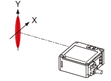
3) The beam diameter is defined as 1/e2 (approx. 13.5 %) of the center light intensity. Due to leak light outside the defined range, the measurement values may be affected if the reflectance around the detecting point is higher than that of the detecting point.
4) This product complies with the FDA regulations (FDA 21 CFR 1040.10 and 1040.11) in accordance with FDA Laser Notice No. 56, except for complying with IEC 60825-1 Ed. 3.
5) Current consumption of the sensor only. External input current is not included.
6) Do not use or store this product in environments where ambient air is pressurized to an air pressure higher than the atmospheric pressure at an altitude of 0 m.
7) The server functionality of SLMP supports both 3E and 4E frames; however, the client functionality only supports 4E frames.
* Ethernet is a registered trademark of FUJIFILM Business Innovation Corp.
* EtherNet/IP is a trademark or a registered trademark of Open DeviceNet Vendors Association (ODVA).
* Modbus is a registered trademark of Schneider Electric USA Inc.
* SLMP is a registered trademark of Mitsubishi Electric Corporation.
Analog output type
| Item | Type | Analog output type | ||||||||||
| Model No. | HL-G203B-A-MK | HL-G205B-A-MK | HL-G208B-A-MK | HL-G212B-A-MK | HL-G225B-A-MK | |||||||
| Applicable regulations and certifications | CE Marking (EMC Directive, RoHS Directive), UKCA Marking (EMC Regulations, RoHS Regulations), FDA Regulation, TÜV SÜD Certification (U.S.A., Canada), Korea KC Mark | |||||||||||
|---|---|---|---|---|---|---|---|---|---|---|---|---|
| Measurement center distance | 30 mm 1.181 in | 50 mm 1.969 in | 85 mm 3.346 in | 120 mm 4.724 in | 250 mm 9.843 in | |||||||
| Measurement range | ±5 mm ±0.197 in | ±10 mm ±0.394 in | ±20 mm ±0.787 in | ±30 mm ±13.78 in | ±150 mm ±5.906 in | |||||||
| Beam Diameter (Note 2)(Note 3) | X-axis: 40 μm 1.575 mil approx. Y-axis: 1,000 μm 39.370 mil approx. | X-axis: 60 μm 2.362 mil approx. Y-axis: 2,000 μm 78.740 mil approx. | X-axis: 90 μm 3.543 mil approx. Y-axis: 3,000 μm 118.110 mil approx. | X-axis: 100 μm 3.937 mil approx. Y-axis: 4,000 μm 157.480 mil approx. | X-axis: 300 μm 11.811 mil approx. Y-axis: 8,000 μm 314.961 mil approx. | |||||||
| Resolution | 0.5μm 0.020 mil | 1.5μm 0.059 mil | 2.5μm 0.098 mil | 4μm 0.157 mil | 15μm 0.591 mil | |||||||
| Linearity | Limited range | ±0.05%F.S. (27.5 mm to 32.5 mm) (1.083 in to 1.280 in) | ±0.05%F.S. (45 mm to 55 mm) (1.772 in to 2.165 in) | ±0.05%F.S. (75 mm to 95 mm) (2.953 in to 3.740 in) | ±0.05%F.S. (105 mm to 135 mm) (4.134 in to 5.315 in) | ±0.15%F.S. (200 mm to 300 mm) (7.874 in to 11.811 in) | ||||||
| Other than above | ±0.075%F.S. | ±0.075%F.S. | ±0.075%F.S. | ±0.075%F.S. | ±0.25%F.S. | |||||||
| Temperature characteristics | 0.03 %F.S./℃ | |||||||||||
| Measuring method | Diffuse reflection | |||||||||||
| Light source | Red semiconductor laser: Class 2 [IEC / EN / JIS / GB / KS / FDA Laser Notice No. 56 (Note 4)] Maximum output: 1 mW, Peak emission wavelength: 655 nm | |||||||||||
| Light receiving element | CMOS image sensor | |||||||||||
| Power supply voltage | Power supply units with a current capacity of 500 mA or more, including 24 V DC ±10 %, ripple 0.5 V (P-P) | |||||||||||
| Current consumption | 150 mA or less (Note 5) | |||||||||||
| Sampling cycle | 100 μs, 200 μs, 500 μs, 1 ms, 2 ms | |||||||||||
| Analog output | Output mode switchable by changing the setting | |||||||||||
| When voltage output is selected | When current output is selected | |||||||||||
| Output scale (Default value) | 0 V to 5 V / F.S. | 4 mA to 20 mA / F.S. | ||||||||||
| Normal output range | 0 V to 5.25 V | 3.2 mA to 20.8 mA | ||||||||||
| Alarm *1 | 5.3 V ± 20 mV | 22 mA ± 100 μA | ||||||||||
| Indeterminate state | 5.5 V ± 20 mV | 23 mA ± 100 μA | ||||||||||
| Impedance | Output impedance: 100 Ω | Load impedance: 300 Ω or less | ||||||||||
| Resolution *2 | ± 2 mV | ± 6 μA | ||||||||||
| Linearity *3 | ±0.05 % F.S. | ±0.25 % F.S. | ||||||||||
| Temperature characteristics | 0.005 % F.S./℃ | 0.01 % F.S./℃ | ||||||||||
| *1: The value that will be output when Alarm analog output is set to Alarm. When set to Hold, the value immediately before alarm occurrence will be held. *2: This refers to the repeatability of analog output only. Static resolution and linearity error by measurement will be added. *3: This refers to the linearity of analog output only. Static resolution and linearity error by measurement will be added. This does not include the repeatability of analog output only. | ||||||||||||
| Control output | OUT 1 OUT 2 OUT 3 | • Possible to switch over between NPN transistor open collector / PNP transistor open collector by changing the setting • Possible to switch over between judgment output and alarm output by changing the setting <When NPN output is selected> • Maximum sink current: 50 mA • Applied voltage: 26.4 V DC or less (between output and 0 V) • Residual voltage: 2 V or less (at 50 mA sink current) • Leakage current: 0.1 mA or less <When PNP output is selected> • Maximum source current: 50 mA • Residual voltage: 2.8 V or less (at 50 mA source current) • Leakage current: 0.1 mA or less | ||||||||||
| Output type | Possible to switch over between open and close when set to ON by changing the setting | |||||||||||
| Protection | Equipped (Automatic recovery type) * This is not an overcurrent protection. | |||||||||||
| External input | IN 1 IN 2 IN 3 | • Possible to switch over from trigger, zero setting, measured value resetting, laser stop, teaching, or bank by changing the setting • The input conditions are interlocked with NPN / PNP setting of the control output <When NPN output is selected> • Source current: 1.5 mA approx. • Input conditions Invalid: 3 to 26.4 V DC or open Valid: 0 to 1.5 V DC <When PNP output is selected> • Sink current: 2.5 mA approx. • Input conditions Invalid: 0 to 11 V DC or open Valid: 19 to 26.4 V DC | ||||||||||
| Indicators | Laser radiation | Green LED (Lit while laser beams are being emitted) | ||||||||||
| Alarm | Orange LED (Lit when measurement is not possible due to insufficient or excessive received light intensity, or due to excessive extraneous light) | |||||||||||
| Display section | 0.9 inch organic EL Measured value: signed 5-digit (maximum of 4 digits after the decimal point) | |||||||||||
| Pollution degree | 2 | |||||||||||
| Operating altitude(Note 6) | 2,000 m 6561.680 ft or less | |||||||||||
| Grounding method | Capacitor grounding | |||||||||||
| Environmental resistance | Protection | IP67 (IEC) | ||||||||||
| Ambient temperature | -10 to +45 ℃ -14 to 113 ℉ (No icing allowed), Storage: -20 to +60 ℃ -4 to 140 ℉ (No icing allowed) | |||||||||||
| Ambient humidity | 35 to 85 % RH (No condensation allowed), Storage: 35 to 85 % RH (No condensation allowed) | |||||||||||
| Ambient illuminance | Incandescent light: 3,000 ℓx or less at the light-receiving face | |||||||||||
| Insulation resistance | 20 MΩ or higher, using 500 V DC megger | |||||||||||
| Withstand voltage | 1,000 V AC between all terminals and case for 1 minute | |||||||||||
| Vibration resistance | 10 to 55 Hz (period: 1 min.) frequency, 1.5 mm 0.059 in double amplitude in X, Y and Z directions for two hours each | |||||||||||
| Shock resistance | 500 m/s2 acceleration (50 G approx.) in X, Y and Z directions three times each | |||||||||||
| Material | Product casing: Aluminum die casting, Front cover: Glass, Cable: PVC | |||||||||||
| Weight | Net weight: 150 g approx., Gross weight: 200 g approx. | |||||||||||
Notes :
1) Unless otherwise specified, the above specifications are typical values measured under the following measurement conditions. They do not guarantee performance for all target objects.
Power supply voltage: 24 V DC, ambient temperature: 20 ℃ 68 ℉, sampling cycle: 1 ms, average count: 512 times, measurement center distance, target object: visible light shielding ceramic
2) The X and Y axes of the beam diameter are specified as shown in the figure follow.
3) The beam diameter is defined as 1/e2 (approx. 13.5 %) of the center light intensity. Due to leak light outside the defined range, the measurement values may be affected if the reflectance around the detecting point is higher than that of the detecting point.
4) This product complies with the FDA regulations (FDA 21 CFR 1040.10 and 1040.11) in accordance with FDA Laser Notice No. 56, except for complying with IEC 60825-1 Ed. 3.
5) Current consumption of the sensor only. External input current is not included.
6) Do not use or store this product in environments where ambient air is pressurized to an air pressure higher than the atmospheric pressure at an altitude of 0 m.
* Ethernet is a registered trademark of FUJIFILM Business Innovation Corp.
* EtherNet/IP is a trademark or a registered trademark of Open DeviceNet Vendors Association (ODVA).
* Modbus is a registered trademark of Schneider Electric USA Inc.
* SLMP is a registered trademark of Mitsubishi Electric Corporation.
------------------------------ Tab6 showing ------------------------------
Dimensions
- Unit: mm in
Sensor
HL-G2□B-S-MK
HL-G2□B-A-MK
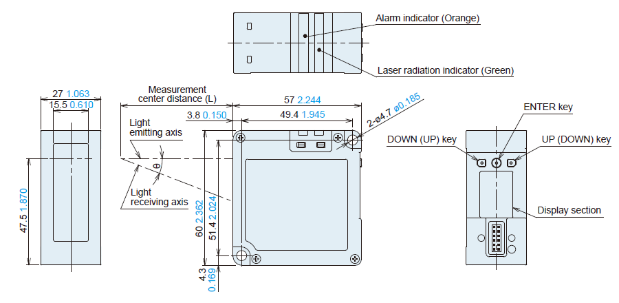
| Model No. | Measurement center distance (L) | θ |
| HL-G203B-S-MK / HL-G203B-A-MK | 30 1.181 | 30° |
| HL-G205B-S-MK / HL-G205B-A-MK | 50 1.969 | 24° |
| HL-G208B-S-MK / HL-G208B-A-MK | 85 3.346 | 17° |
| HL-G212B-S-MK / HL-G212B-A-MK | 120 4.724 | 13° |
| HL-G225B-S-MK / HL-G225B-A-MK | 250 9.843 | 6.5° |
Optional Cable for Ethernet Communication (Sold Separately)
CN-8E-C□
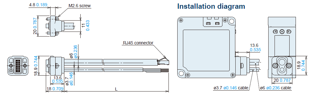
Model No. : Length L
CN-8E-C2: 2,000 78.740
CN-8E-C5 :5,000 196.850
Optional Cable for RS-485 Communication (Sold Separately)
CN-8R-C□

Model No. : Length L
CN-8R-C2: 2,000 78.740
CN-8R-C5: 5,000 196.850
CN-8R-C10: 10,000 393.701
CN-8R-C20: 20,000 787.402
Optional Cable for Analog Output Type (Sold Separately)
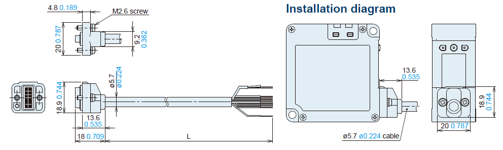
Model No. : Length L
CN-8A-C2: 2,000 78.740
CN-8A-C5: 5,000 196.850
------------------------------ Tab7 showing ------------------------------
Circuit/ Wiring
Example of system configuration
Communication type
Ethernet communication
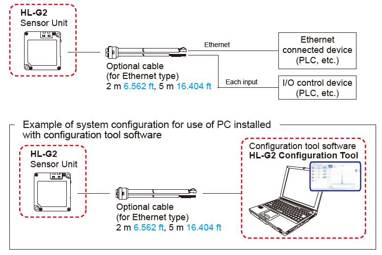
RS-485 communication

・RS-485 wiring allows connection of up to 16 devices.
・When RS-485 wiring is used for the converter, be sure to check for proper operation using actual equipment before using.
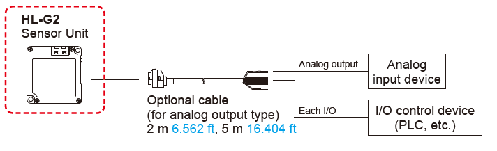
Analog output type
------------------------------ Tab8 showing ------------------------------
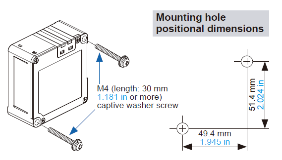
Sensor installation
Use M4 screws with captive washers (length: 30 mm 1.181 in or longer) (not provided with product) for the installation of the product. The tightening torque should be 0.8 N∙m or less.
Beam diameter
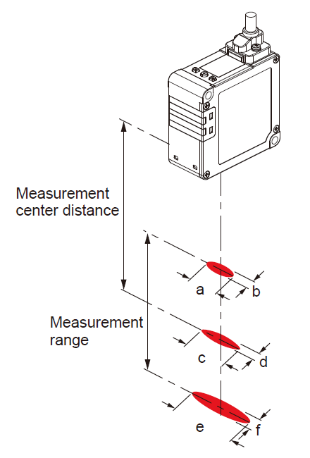
| Model No. | Beam diameter (Unit: mm in) | |||||
| a | b | c | d | e | f | |
| HL-G203B-S-MK / HL-G203B-A-MK | 0.7 0.028 | 0.1 0.004 | 1.0 0.039 | 0.04 0.002 | 1.3 0.051 | 0.1 0.004 |
|---|---|---|---|---|---|---|
| HL-G205B-S-MK / HL-G205B-A-MK | 1.2 0.047 | 0.2 0.008 | 2.0 0.079 | 0.06 0.002 | 2.8 0.110 | 0.2 0.008 |
| HL-G208B-S-MK / HL-G208B-A-MK | 2.0 0.079 | 0.3 0.012 | 3.0 0.118 | 0.09 0.004 | 4.0 0.157 | 0.2 0.008 |
| HL-G212B-S-MK / HL-G212B-A-MK | 2.8 0.110 | 0.3 0.012 | 4.0 0.157 | 0.1 0.004 | 5.2 0.205 | 0.3 0.012 |
| HL-G225B-S-MK / HL-G225B-A-MK | 2.5 0.098 | 0.7 0.028 | 8.0 0.315 | 0.3 0.012 | 13.5 0.531 | 0.5 0.020 |
- This product is classified as a Class 2 Laser Product under IEC / EN / JIS / GB / KS standards and FDA * regulations. Do not look at the laser beam directly or through an optical system such as a lens.
- Based on the safety standards for laser products, FDA / IEC (EN) standard certification / identification / warning labels are affixed to both sides of this product.

- This product is shipped with JIS, GB, and KS standard warning labels. Affix appropriate labels over the FDA / IEC (EN) labels as needed.