------------------------------ Tab1 showing ------------------------------
Basic Information
More Extensive Applications
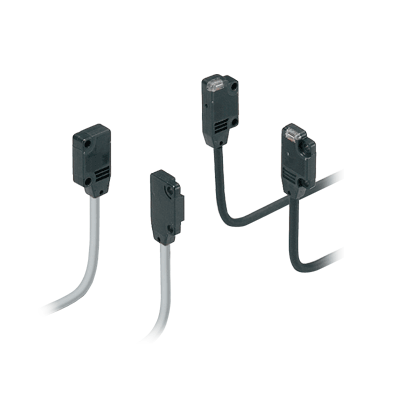
Introducing narrow-beam type models for the EX-10 series of ultra-slim photoelectric sensors


UL,CE,UKCA Approved
UL : Recognition
*Be sure to read the "Cautions For Use" when using for the above applications.
*Before using this device, be sure to confirm the standards / regulations applied in the relevant nation and region.
*If you need the Certificate or Confirmation Letter, please contact us.![]()
Features
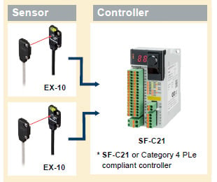
Sensor unit complies with ISO 13849-1*1 Category 1 PLc*2 
A Category 3 PLd Safety System can be built by using Category 4 PLe compliant controllers together with our sensors
*1 Safety-related parts of control systems, Part 1: General principles for design
*2 Conformed from December 2021 production.
■ Category 3, PLd construction example
[Precautions when using as Category 3 PLd]
Sensor redundancy is required!
Observe the following when connecting to the safety controller.
・In the case the product is used in a standalone state, the safety system may not operate properly when a sensor malfunction occurs.
CAUTION
The product cannot be used for human body detection.
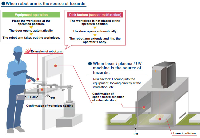
■ Application examples
[Required conditions]
1.The source of hazards is located inside the machine and may cause hazards to nearby people.
2.The equipment is classified as Category 3 PLd or lower.
3.The source of hazards is isolated only by the automatic door.
* The product can be used safely when all of the above conditions 1 through 3 are satisfied!
* There are cases where you can use it under other conditions.
*Be sure to read the "Cautions For Use" when using for safety applications.
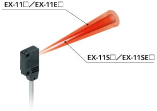
Alleviates interference without slits, allowing close-spaced installation
With about half the light diffusion of previous models, narrow-beam models can be placed twice as closely together-without the added cost of purchasing and installing slits.
Detects minute objects with a diameter of just 0.5 mm 0.020 in, without slits [EX-11S□]
With about half the light diffusion of previous models, narrow-beam models can detect minute objects with a diameter of just 0.5 mm 0.020 in, without slits.
These models provide a reasonably-priced solution for applications requiring detection of minute objects.
![Detects minute objects with a diameter of just 0.5 mm 0.020 in, without slits [EX-11S□]](https://tp.industry.panasonic.com/hubfs/pid-corp/products/fasys/sensor/photoelectric/ex-10s/images/pic03.jpg)
Long-range sensing at 1 m 3.281 ft with a narrow-beam [EX-19S□]
Narrow-beam models deliver long-range sensing at 1 m 3.281ft.
Application Example:Detecting PCB rack
![Long-range sensing at 1 m 3.281 ft with a narrow-beam [EX-19S□]](https://tp.industry.panasonic.com/hubfs/pid-corp/products/fasys/sensor/photoelectric/ex-10s/images/pic04.jpg)
------------------------------ Tab2 showing ------------------------------
------------------------------ Tab3 showing ------------------------------
------------------------------ Tab4 showing ------------------------------
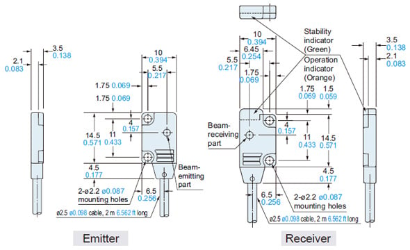
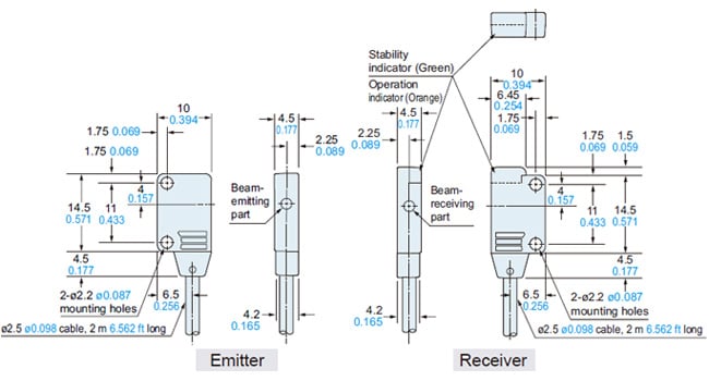
Dimensions
- Unit: mm in
EX-11S□
EX-13S□
EX-19S□
Sensor
EX-11SE□
EX-13SE□
Sensor
------------------------------ Tab5 showing ------------------------------
I/O Circuit and Wiring diagrams
NPN output type
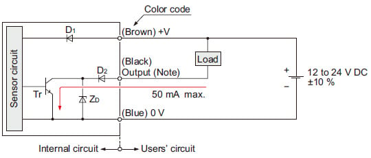
Note: The emitter does not incorporate the output.
Symbols・・・
D1: Reverse supply polarity protection diode
D2: Reverse output polarity protection diode
ZD: Surge absorption zener diode
Tr : NPN output transistor
PNP output type
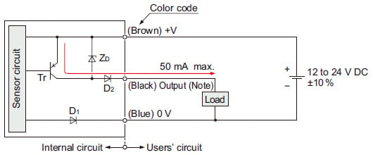
Note: The emitter does not incorporate the output.
Symbols・・・
D1: Reverse supply polarity protection diode
D2: Reverse output polarity protection diode
ZD: Surge absorption zener diode
Tr : NPN output transistor
------------------------------ Tab6 showing ------------------------------
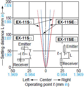
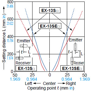
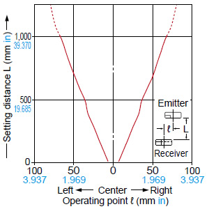
Sensing characteristics
PARALLEL DEVIATIONS (TYPICAL)
EX-11S□ / EX-11SE□
EX-13S□ / EX-13SE□
EX-19S□
------------------------------ Tab7 showing ------------------------------
Mounting
- In case of mounting on tapped holes (Unit: mm in)
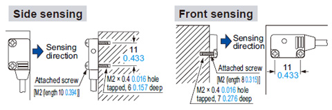
The tightening torque should be 0.2 N·m or less.
- In case of using attached screws and nuts (Unit: mm in)
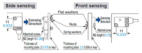
The tightening torque should be 0.2 N·m or less.
Others
- This product has been developed / produced for industrial use only.
- This product is suitable for indoor use only.
- Do not use during the initial transient time (50 ms) after the power supply is switched on.
- Excess bending of the cable or stress applied to the cable may disconnect the internal lead wire.