Discontinued Products

Specifications
Sensor units
| Number of beam channels | 8 | 16 | 24 | 32 | |
|---|---|---|---|---|---|
| Model No. | SF1-A8 | SF1-A16 | SF1-A24 | SF1-A32 | |
| With spatter protection hood | SF1-A8-H | SF1-A16-H | SF1-A24-H | SF1-A32-H | |
| Applicable control units | SF1-AC1, SF1-AC2 | ||||
| Sensing height | 140mm | 300mm | 460mm | 620mm | |
| Sensing range | 5m | ||||
| Beam pitch | 20mm | ||||
| Sensing object | ø30mm or more opaque object | ||||
| Indicators | Emitter | Emitting indicator: Green LED (lights up under normal emission, blinks under emitting circuit failure) | |||
| Receiver (Note) | Operation indicator: Red LED (lights up when one or more beams are interrupted, and blinks when extraneous light is received) Stable incident beam indicator: Green LED (lights up when all beams are received stably) Unstable incident beam indicator: Yellow LED (lights up when one or more beams are received unstably) * The three color indicators blink in rotation when the receiving circuit fails. The operation indicator and the unstable incident beam indicator blink alternately when the emitting circuit fails or the synchronization wire breaks. | ||||
| Interference prevention function | Incorporated (Two units of sensors can be mounted closely.) | ||||
| Automatic sensitivity compensation function | Incorporated | ||||
| Environmental resistance | Pollution degree | 3 (Industrial environment) | |||
| Protection | IP65 (IEC) | ||||
| Ambient temperature | -10 to +55℃ (No dew condensation or icing allowed), Storage: -10 to +60℃ | ||||
| Ambient humidity | 35 to 85% RH, Storage: 35 to 85% RH | ||||
| Ambient illuminance | Sunlight: 20,000lx at the light-receiving face, Incandescent light: 3,500lx at the light-receiving face | ||||
| EMC | Emission/Immunity: prEN50100-1 | ||||
| Voltage withstandability | 1,000V AC for one min. between all supply terminals connected together and enclosure | ||||
| Insulation resistance | 20MΩ, or more, with 500V DC megger between all supply terminals connected together and enclosure | ||||
| Vibration resistance | 10 to 55Hz frequency, 1.5mm amplitude in X, Y and Z directions for two hours each | ||||
| Shock resistance | 100m/s2 acceleration (10G approx.) in X, Y and Z directions for three times each | ||||
| Emitting element | Infrared LED (modulated) | ||||
| Material | Protection enclosure: Aluminum, Module case: ABS, Front cover: Acrylic, Lens: Acrylic | ||||
| Cable | 0.5mm2 4-core cabtyre cable, 0.5m long, with a round connector at the end * Use together with the optional mating cable | ||||
| Cable extension | Extension up to total 20m is possible, for both emitter and receiver, with 0.5mm2, or more, cable. | ||||
| Weight | 500g approx. | 840g approx. | 1,170g approx. | 1,500g approx. | |
| With spatter protection hood | 630g approx. | 1,080g approx. | 1,530g approx. | 1,990g approx. | |
| Accessory | MS-SF1-1 (Sensor unit mounting bracket): 1 set | ||||
(Note) :
The indicators on the receiver operate as follows depending on the incident light intensity.

| Number of beam channels | 40 | 48 | 56 | 64 | |
|---|---|---|---|---|---|
| Model No. | SF1-A40 | SF1-A48 | SF1-A56 | SF1-A64 | |
| With spatter protection hood | SF1-A40-H | SF1-A48-H | SF1-A56-H | SF1-A64-H | |
| Applicable control units | SF1-AC1, SF1-AC2 | ||||
| Sensing height | 780mm | 940mm | 1,100mm | 1,260mm | |
| Sensing range | 5m | ||||
| Beam pitch | 20mm | ||||
| Sensing object | ø30mm or more opaque object | ||||
| Indicators | Emitter | Emitting indicator: Green LED (lights up under normal emission, blinks under emitting circuit failure) | |||
| Receiver (Note) | Operation indicator: Red LED (lights up when one or more beams are interrupted, and blinks when extraneous light is received) Stable incident beam indicator: Green LED (lights up when all beams are received stably) Unstable incident beam indicator: Yellow LED (lights up when one or more beams are received unstably) * The three color indicators blink in rotation when the receiving circuit fails. The operation indicator and the unstable incident beam indicator blink alternately when the emitting circuit fails or the synchronization wire breaks. | ||||
| Interference prevention function | Incorporated (Two units of sensors can be mounted closely.) | ||||
| Automatic sensitivity compensation function | Incorporated | ||||
| Environmental resistance | Pollution degree | 3 (Industrial environment) | |||
| Protection | IP65 (IEC) | ||||
| Ambient temperature | -10 to +55℃ (No dew condensation or icing allowed), Storage: -10 to +60℃ | ||||
| Ambient humidity | 35 to 85% RH, Storage: 35 to 85% RH | ||||
| Ambient illuminance | Sunlight: 20,000lx at the light-receiving face, Incandescent light: 3,500lx at the light-receiving face | ||||
| EMC | Emission/Immunity: prEN50100-1 | ||||
| Voltage withstandability | 1,000V AC for one min. between all supply terminals connected together and enclosure | ||||
| Insulation resistance | 20MΩ, or more, with 500V DC megger between all supply terminals connected together and enclosure | ||||
| Vibration resistance | 10 to 55Hz frequency, 1.5mm amplitude in X, Y and Z directions for two hours each | ||||
| Shock resistance | 100m/s2 acceleration (10G approx.) in X, Y and Z directions for three times each | ||||
| Emitting element | Infrared LED (modulated) | ||||
| Material | Protection enclosure: Aluminum, Module case: ABS, Front cover: Acrylic, Lens: Acrylic | ||||
| Cable | 0.5mm2 4-core cabtyre cable, 0.5m long, with a round connector at the end * Use together with the optional mating cable | ||||
| Cable extension | Extension up to total 20m is possible, for both emitter and receiver, with 0.5mm2, or more, cable. | ||||
| Weight | 1,830g approx. | 2,170g approx. | 2,500g approx. | 2,830g approx. | |
| With spatter protection hood | 2,440g approx. | 2,900g approx. | 3,350g approx. | 3,800g approx. | |
| Accessory | MS-SF1-1 (Sensor unit mounting bracket): 1 set | ||||
(Note) :
The indicators on the receiver operate as follows depending on the incident light intensity.
Control units
| Type | AC power operation | DC power operation | |
|---|---|---|---|
| Model No. | SF1-AC1 | SF1-AC2 | |
| Applicable sensor units | SF1-A□, SF1-A□-H | ||
| Supply voltage | 100 to 240V AC 50 to 60Hz | 24V DC±15% Ripple P-P 10% or less | |
| Power/Current consumption | 24VA or less (including the sensor unit) | 1A or less (including the sensor unit) | |
| Sensing outputs (FSD1、FSD2) | Relay contact 1a (Two outputs) ・Switching capacity: 250V 1.5A AC (resistive load) 30V 3A DC (resistive load) ・Electrical life: 100,000 operations or more (rated load, switching frequency 20 cycles/min.) ・Mechanical life: 10,000,000 operations or more (switching frequency 180 cycles/min.) | Relay contact 1a (Two outputs) ・Switching capacity: 30V 3A DC (resistive load) ・Electrical life: 100,000 operations or more (rated load, switching frequency 20 cycles/min.) ・Mechanical life: 10,000,000 operations or more (switching frequency 180 cycles/min.) | |
| Utilization category | - | DC-12 or DC-13 | |
| Output operation | ON (closed) when all beams are received/OFF (open) when one or more beams are interrupted In case of any failure of the sensor unit or if the system goes into the lockout condition, the output relays are turned off. (Note 1) | ||
| Response time | 20ms or less (including sensor unit's response time) | ||
| Lockout output (SSD) | Relay contact 1a ・Switching capacity: 250V 1.5A AC (resistive load) 30V 3A DC (resistive load) ・Electrical life: 100,000 operations or more (rated load, switching frequency 20 cycles/min.) ・Mechanical life: 10,000,000 operations or more (switching frequency 180 cycles/min.) | - | |
| Output operation | ON (closed) in the normal condition/ OFF (open) in the lockout condition (Note 2) | - | |
| Response time | 500ms or less | - | |
| Monitor output | - | Relay contact 1b ・Switching capacity: 30V 3A DC (resistive load) ・Electrical life: 100,000 operations or more (rated load, switching frequency 20 cycles/min.) ・Mechanical life: 10,000,000 operations or more (switching frequency 180 cycles/min.) | |
| Output operation | - | ON (open) when all beams are received/ OFF (closed) when one or more beams are interrupted In case of any failure of the sensor unit or if the system goes into the lockout condition, the output relay is turned off (Note 3). | |
| Response time | - | 20ms or less | |
| Input | Non-voltage contact ・Lockout release input: Lockout is released by a short-circuit between terminals ・External lockout input: System goes into the lockout condition by an open between terminals ・External FSD-OFF input: FSDs are turned off by a short-circuit between terminals ・Muting input: System is muted by a short-circuit between terminals of both the muting inputs ・Monitor input: The system goes into the lockout condition when the MPCE and the FSD status do not match (dual circuits) | Non-voltage contact ・Test input: Emission is stopped by an open between terminals ・Restart input: Open between the terminals maintains FSDs in OFF state. ・Monitor input: The system goes into the lockout condition when the MPCE and the FSD status do not match (dual circuits) | |
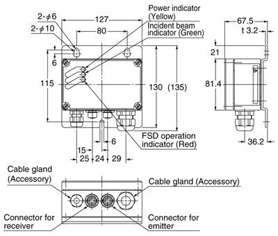
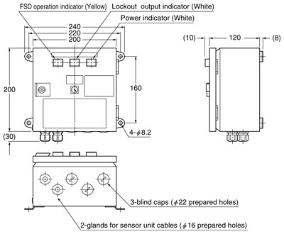
| Indicators | Power indicator: White (lights up when the power is ON) Lockout output indicator: White (lights up in the lockout condition) FSD operation indicator: Yellow (lights up when FSDs are OFF) | Power indicator: Yellow LED (lights up when the power is ON) Incident beam indicator: Green LED (lights up when FSDs are ON) FSD operation indicator: Red LED (lights up when FSDs are OFF) * All indicators light up in the lockout condition | |
| Environmental resistance | Pollution degree | - | 3 (Industrial environment) |
| Protection | IP65 (IEC) | ||
| Ambient temperature | -10 to +55℃ (No dew condensation or icing allowed), Storage: -10 to +60℃ | ||
| Ambient humidity | 35 to 85% RH, Storage: 35 to 85% RH | ||
| EMC | - | Emission/Immunity: prEN50100-1 | |
| Voltage withstandability | 1,500V AC for one min. between AC inputs and DC outputs | 1,500V AC for one min. between all supply terminals connected together and enclosure | |
| Insulation resistance | 20MΩ, or more, with 500V DC megger between AC inputs and DC outputs | 20MΩ, or more, with 500V DC megger between all supply terminals connected together and enclosure | |
| Vibration resistance | 10 to 55Hz frequency, 2G constant in X, Y and Z directions for one hour each | ||
| Shock resistance | 100m/s2 acceleration (10G approx.) in X, Y and Z directions for three times each | ||
| Material | Mild steel plate | Diecast aluminum | |
| Weight | 3.5kg approx. | 2kg approx. | |
| Accessories | SF1-AC-TL (Test rod): 1 No. NA-BC-K2 (Front cover key): 1 No. NA-BC-K3 (Lockout release key): 1 No. MEHS-SF1A (System information plate): 1 No. | SF1-AC-TL (Test rod): 1 No. Cable gland (for ø4 to ø8mm cable dia.): 1 No. | |
(Note 1) :
Under the following conditions, the FSDs (sensing output) are turned off.
(1)When one or more beams are interrupted [unless the sensor unit is muted (SF1-AC1 only)].
(2)When the sensor unit falls into an abnormal condition (sensor failure) [unless the sensor unit is muted. (SF1-AC1 only)].
(3)When the sensor unit receives intense ambient light [unless the sensor unit is muted (SF1-AC1 only)].
(4)When the sensor unit cable or the mating cable is broken or short-circuited [unless the sensor unit is muted (SF1-AC1 only)].
(5)When the external FSD-OFF input is short-circuited (SF1-AC1 only).
(6)When the test input terminals are open (SF1-AC2 only).
(Note 2) :
Under the following conditions, the SSD (lockout output) incorporated in SF1-AC1 is turned off.
(1)When commencing operation or when supplying power again after power disconnection.
(2)When one of the FSD relay contacts gets welded.
(3)When one of the MPCE relay contacts gets welded.
(4)When the results of the dual circuits incorporated in the control unit are different.
(5)When the external lockout input is open.
(6)When the MPCE operation (NO/NC) is different from the setting of the MPCE operation mode selection switch in the control unit.
(Note 3) :
Under the following conditions, the monitor output incorporated in SF1-AC2 is turned off.
(1)When one or more beams are interrupted.
(2)When the sensor unit falls into an abnormal condition.
(3)When the sensor unit receives an intense extraneous light.
(4)When the sensor unit cable or the mating cable is broken or short-circuited.
(5)When the test input is opened (emission stopped).
(Note 4) :
The muting input (SF1-AC1 only) cancels the sensor operation so that any beam interruption cannot make the FSD output relays open. This function is used to make the sensor temporarily inoperable for feeding a workpiece into a machine or removing it. This input must be carefully handled.
Dimensions
- Unit: mm in
SF1-A□
Sensor unit
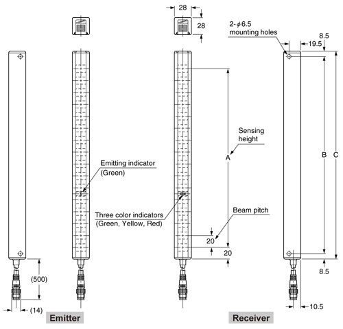
| Model No. | A | B | C |
|---|---|---|---|
| SF1-A8 | 140 | 172 | 189 |
| SF1-A16 | 300 | 332 | 349 |
| SF1-A24 | 460 | 492 | 509 |
| SF1-A32 | 620 | 652 | 669 |
| SF1-A40 | 780 | 812 | 829 |
| SF1-A48 | 940 | 972 | 989 |
| SF1-A56 | 1,100 | 1,132 | 1,149 |
| SF1-A64 | 1,260 | 1,292 | 1,309 |
SF1-A□-H
Sensor unit
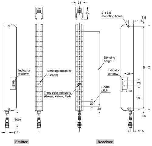
| Model No. | A | B | C |
|---|---|---|---|
| SF1-A8-H | 140 | 172 | 189 |
| SF1-A16-H | 300 | 332 | 349 |
| SF1-A24-H | 460 | 492 | 509 |
| SF1-A32-H | 620 | 652 | 669 |
| SF1-A40-H | 780 | 812 | 829 |
| SF1-A48-H | 940 | 972 | 989 |
| SF1-A56-H | 1,100 | 1,132 | 1,149 |
| SF1-A64-H | 1,260 | 1,292 | 1,309 |
SF1-AC1
Control unit
SF1-AC2
Control unit