LC4H-W Electronic Counters(DIN 48) (Discontinued Products)
Download
-
Discontinued Products
-
Rating/ Performance
-
Dimensions
-
Cautions For Use
-
Wiring/ Connection
Ⅾiscontinued
Last time buy (JST)
March 31, 2023
------------------------------ Tab1 showing ------------------------------
Discontinued Products

------------------------------ Tab2 showing ------------------------------
Rating/ Performance
| Item | Ralay output type | Transistor output type | ||||
|---|---|---|---|---|---|---|
| AC type | DC type | AC type | DC type | |||
| Rating | Rated operating voltage | 100 to 240 V AC 24 V AC | 12 to 24 V DC | 100 to 240 V AC 24 V AC | 12 to 24 V DC | |
| Rated frequency | 50/60 Hz common | - | 50/60 Hz common | - | ||
| Power consumption | Max. 10 V A | Max. 3 W | Max. 10 V A | Max. 3 W | ||
| Rated control capacity | 3 A, 250 V AC (resistive load) | 100 mA, 30 V DC | ||||
| Input mode | Addition (UP)/Subtraction (DOWN)/Direction (DIR)/Individuality (IND)/Phase (PHASE) 5 modes selectable by DIP switch | |||||
| Counting speed | 30 Hz(cps)/5 KHz(cps) (selectable by DIP switch) | |||||
| Counting input (Input 1, 2) | Min. input signal width: 16.7 ms at 30 Hz(cps)/0.1 ms at 5 KHz(cps) ON time: OFF time = 1:1 | |||||
| Reset input method | Min. input signal width: 1 ms, 20 ms (selected by DIP switch) | |||||
| Input signal | Contact or Open collector input/Input impedance: 1 kΩ or less, Input residual voltage: 2 V or less, Open impedance: 100 kΩ or less, Max. energized voltage: 40 V DC | |||||
| Output mode | Output 1. HOLD-B, C, D SHOT-A (4 modes) Output 2. HOLD-A, B, C SHOT-A, B, C, D (8 modes) (selectable by DIP switch) | |||||
| One shot output time | Approx. 1 s | |||||
| Indication | 7-segment LCD, Counter value (backlight red LED), Setting value (backlight yellow LED) | |||||
| Digit | -99999 to 999999 (-5 digits to 6 digits) (0 to 999999 for setting) | |||||
| Memory | EEP-ROM (Overwriting times: 105ope. or more) | |||||
| Contact | Contact arrangement | 1 Form A + 1 Form A | 1 Form A + 1 Form A (Open collector) | |||
| Contact resistance (Intial value) | 100 mΩ (at 1 A 6 V DC) | - | ||||
| Contact material | Ag alloy/Au flush | - | ||||
| Life | Mechanical(contact) | Min. 2.0×10⁷ope. | - | |||
| Electrical(contact) | Min. 1.0×10⁵ope. (At rated control voltage) | Min. 1.0×10⁷ope. (At rated control voltage) | ||||
| Electrical | Allowable operating voltage range | 85 to 110 % of rated operating voltage | ||||
| Break down voltage (Initial value) | Between live and dead metal parts: 2, 000 Vrms for 1 min (pin type) Between input and output: 2, 000 Vrms for 1 min Between open contacts: 1, 000 Vrms for 1 min | Between live and dead metal parts: 2, 000 Vrms for 1 min Between input and output: 2, 000 V AC for 1 min | ||||
| Insulation resistance (At 500 V DC) (Initial value) | Between live and dead metal parts: Min. 100 MΩ (pin type) Between input and output: Min. 100 MΩ Between open contact: Min. 100 MΩ | Between live and dead metal parts: Min. 100 MΩ (pin type) Between input and output: Min. 100 MΩ | ||||
| Temperature rise | Max. 65°C (under the flow of nominal operating current at nominal voltage) | - | ||||
| Mechanical | Vibration resistance | Functional | 10 to 55 Hz (1 cycle/min), single amplitude: 0.35 mm .014 inch (10 min on 3 axes) | |||
| Destructive | 10 to 55 Hz (1 cycle/min), single amplitude: 0.75 mm .030 inch (1 h on 3 axes) | |||||
| Shock resistance | Functional | Min. 98 m/s2 321.522 ft./s2(4 times on 3 axes) | ||||
| Destructive | Min. 294 m/s2 964.567 ft./s2(5 times on 3 axes) | |||||
| Operating conditions | Ambient temperature | -10°C to 55°C/ +14 ° F to +131 ° F | ||||
| Ambient humidity | Max. 85 % RH (non-condensing) | |||||
| Air pressure | 860 to 1, 060 h Pa | |||||
| Ripple rate | - | 20 % or less | - | 20 % or less | ||
| Connection | 11-pin/screw terminal | |||||
| Protective construction | IP66 (front panel with a rubber gasket) | |||||
------------------------------ Tab3 showing ------------------------------
Dimensions
- Unit: mm in
LC4H-W electrical counter
General tolerance : ±1.0 ±0.39

Dimensions for embedded installation (with adapter installed)

Dimensions for front panel installations
Installation panel cut-out dimensions
The standard panel cut-out dimensions are shown below. Use the installation frame (ATA4811) and rubber gasket (ATC18002).
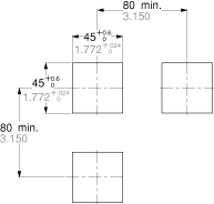
For connected installations
*1 The installation panel thickness should be between 1 and 5 mm/ .039 and .197 inch.*2 For connected installations, the waterproofing ability between the unit and installation panel is lost.
------------------------------ Tab4 showing ------------------------------
Cautions For Use
Protective circuit for timer contact
In the circuit that switches an inductive load, a contact failure may occur at a contact point due to surge or inrush current resulting from that switching. Therefore, it is recommended that the following protective circuit be used to protect the contact point.
| CR circuit (r: resistor c: capacitor) | |||
|---|---|---|---|
| Circuit |
|
| |
| Application | AC | * Note: | Available |
| DC | Available | Available | |
| Features/Others | If the load is a relay or solenoid, the release time lengthens. Effective when connected to both contacts if the power supply voltage is 24 or 48 V and the voltage across the load is 100 to 200 V. | ||
| If the load is a timer, leakage current flows through the CR circuit causing faulty operation. Note: If used with AC voltage, be sure the impedance of the load is sufficiently smaller than that of the CR circuit. | - | ||
| Device Selection | As a guide in selecting r and c, c: 0.5 to 1 µF per 1 A contact current r: 0.5 to 1 ohm per 1 V contact voltage Values vary depending on the properties of the load and variations in timer characteristics. Capacitor c acts to suppress the discharge the moment the contacts open. Resistor r acts to limit the current when the power is turned on the next time. Test to confirm. Use a capacitor with a breakdown voltage of 200 to 300 V. Use AC type capacitors (non-polarized) for AC circuits. | ||
| Diode circuit | Varistor circuit | ||
|---|---|---|---|
| Circuit |
|
| |
| Application | AC | Not Available | Available |
| DC | Available | Available | |
| Features/Others | The diode connected in parallel causes the energy stored in the coil to flow to the coil in the form of current and dissipates it as joule heat at the resistance component of the inductive load. This circuit further delays the release time compared to the CR circuit. (2 to 5 times the release time listed in the catalog) | Using the rated voltage characteristics of the varistor, this circuit prevents excessively high voltages from being applied across the contacts. This circuit also slightly delays the release time. Effective when connected to both contacts if the power supply voltage is 24 or 48 V and the voltage across the load is 100 to 200 V. | |
| Device Selection | Use a diode with a reverse breakdown voltage at least 10 times the circuit voltage and a forward current at least as large as the load current. In electronic circuits where the circuit voltages reverse breakdown voltage of about 2 to 3 times the power supply voltage. | - | |
Type of Load and Inrush Current
The type of load and its inrush current characteristics, together with the switching frequency are important factors which cause contact welding. Particularly for loads with inrush currents, measure the steady state current and inrush current and use a relay or magnet switch which provides an ample margin of safety. The table below shows the relationship between typical loads and their inrush currents.
| Type of load | Inrush current |
|---|---|
| Resistive load | Steady state current |
| Solenoid load | 10 to 20 times the steady state current |
| Motor load | 5 to 10 times the steady state current |
| Incandescent lamp load | 10 to 15 times the steady state current |
| Mercury lamp load | 1 to 3 times the steady state current |
| Sodium vapor lamp load | 1 to 3 times the steady state current |
| Capacitive load | 20 to 40 times the steady state current |
| Transformer load | 5 to 15 times the steady state current |
When you want large load and long life of the counter, do not control the load direct with a timer. When the timer is designed to use a relay or a magnet switch, you can acquire the longer life of the counter.
Connection of input (Except for LC4H-S/AC type)
Since LC4H series counters use a transformerless power supply system, the input equipments must have the power supply transformer in which the secondary side is not grounded with the primary and secondary sides insulated, in order to prevent interference of the power supply circuit when connecting the external input circuit as Fig. A.
Be sure not to use an autotransformer. In case of secondary side grounded or using the autotransformer, this product may be destroyed due to short circuit electrically as Fig. B (1 and 2).
In case of F.G. terminal of equipments such a PLC grounded in secondary side of the transformer, inner circuits of this product and the input equipment may be destroyed due to short circuit electrically as Fig.B (3).
Therefore, use the isolated type counters or do not ground F.G. terminal of the products.


Long Continuous Current Flow
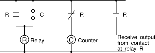
Avoid keeping the counter on for a long period of time (over one month). Otherwise heat is generated and accumulated inside the counter, which may deteriorate its electronic parts. If the counter must be kept on for a long period of time, a relay is added. See the circuit diagram below.
Leakage current
- 1.For connecting and disconnecting operating voltage to the counter, a circuit should be used, which will prevent the flow of leakage current. For example, a circuit for contact protection as shown in Fig A. will permit leakage current flow through R and C, causing erroneous operation of the counter. Instead, the circuit shown in Fig. B should be used.

- 2.If the counter is directly switched with a non-contact element, leak current may flow into the counter and cause it to malfunction.
Pin connections
Correctly connect the pins while seeing the pin layout/connection diagram. In particular, the DC type, which has polarities, does not operate with the polarities connected reverse. Any incorrect connection can cause abnormal heating or ignition.
Connection to operation power supply
- 1.Apply the entire supply voltage through a switch, relay or other contact.
- 2.The operation voltage for the DC type must be at the specified ripple percentage or less. The average voltage must fall within the allowable operation voltage range.
| Rectification type | Ripple percentage |
|---|---|
| Single-phase, full-wave | Approx. 48% |
| Three-phase, full-wave | Approx. 4% |
| Three-phase, half-wave | Approx. 17% |
- 3.Make sure that no induced voltage and residual voltage are applied between the power pins on the timer after the power switch is turned OFF.
(If the power line is wired in parallel with the high-voltage and motor lines, induced voltage may be produced between the power pins.)
Control output
- 1.Keep the load capacity below the counter's rated control capacity. If used above the rating, the counter's service life may shorten. With the transistor output type counters, transistors may be damaged.
Installing the counter
- 1.To install the counter, use the dedicated pin bracket or socket (cap). Avoid connecting the pins on the counter by directly soldering them.
- 2.In order to maintain the characteristics, do not remove the counter cover (case).
Superimposed surge of power supply
For the superimposed surge of power supply, the standard waveform (±1.2×50μs or ±1×40μs) is taken as the standard value for surge-proof voltage.
(The positive and negative voltages are applied each three or five times between the power pins.) For the standard values for the LC4H type counters, see the respective items in "Caution on usage."

If external surge occurs exceeding the specified value, the internal circuit may break down. In this case, use a surge absorption element. The typical surge absorption elements include a varistor, a capacitor, and a diode. If a surge absorption element is used, use an oscilloscope to see whether or not the foreign surge exceeding the specified value appears.
Signal input
The counter's signal input comes in two ways. One is by opening and closing the input terminal. The other is by applying a specified H-level or L-level voltage to the input terminal.
For an input sensor's residual voltage, input impedance, input voltage level and other signal input conditions, see the ratings for each type of product.
Operating environment
- 1.For the ambient operating temperature and humidity, see the ratings for each type of product.
- 2.Avoid using the counter in a location where (a) inflammable or corrosive gas is generated, (b) the counter is exposed to much dust and other foreign matter; (c) water or oil is splashed on the counter; or (d) vibrations or shocks are given to the counter.
- 3.The counter cover (case), the knobs, and the dials are made of polycarbonated resin. Therefore, prevent the counter from being exposed to organic solvents such as methyl alcohol, benzine, and thinner, strong acid substances such as caustic soda, and ammonia and avoid using the counter in atmosphere containing any of those substances.
- 4.If the counter is used where noises are emitted frequently, separate the input signal elements (such as a sensor), the wiring for the input signal line, and the counter as far as possible from the noise source and the high power line containing noises.

Checking the actual load
In order to increase the reliability in the actual use, check the quality of the counter in the actual usage.
Others
- 1. If the counter is used exceeding the ratings (operation voltage and control capacity), the contact life, or any other specified limit, abnormal heat, smoke, or ignition may occur.
- 2.The LC2H series counter, which provides a power failure compensation capability, incorporates a lithium battery.
Never disassemble the lithium battery or throw it into fire because this may affect humans and facilities. The lithium battery must be disposed of as an incombustible like other used batteries. - 3.If any malfunction of the counter is likely to affect human life and properties, give allowance to the rated values and performance values. In addition, take appropriate safety measures such as a duplex circuit from the viewpoint of product liabilities.
Precautions during usage
1.Terminal wiring
- 1.When wiring the terminals, refer to the terminal layout and wiring diagrams and be sure to perform the wiring properly without errors.
- 2.When using the instrument with an embedded installation, the screw-down terminal type is recommended. For the pin type, use either the rear terminal block (AT8-RR) or the 8P cap (AD8-RC) for the 8-pin type, and the 11P cap (AT8-DP11) for the 11-pin type. Avoid soldering directly to the round pins on the unit. When using the instrument with a front panel installation, use the DIN rail terminal block (ATC18003) for the 8-pin type and the DIN rail terminal block (ATC18004) for the 11-pin type.
- 3.After turning the unit off, make sure that any resulting induced voltage or residual voltage is not applied to power supply terminals (2) through (7) (8pin type)(2) through (10) (11pin type) or [1] and [2] (screw-down terminal type). (If the power supply wire is wired parallel to the high voltage wire or power wire, an induced voltage may be generated between the power supply terminals.)
- 4.Have the power supply voltage pass through a switch or relay so that it is applied at one time. If the power supply is applied gradually, the counting may malfunction regardless of the settings, the power supply reset may not function, or other such unpredictable occurrence may result.
2.Input connections
The power circuit has no transformer. When an input signal is applied to two or more timers at once, do not operate the power circuit in an independent way. If the timer is powered on and off independently as shown in Fig.A, the timer's internal devices may get damaged. Be careful never to allow such wiring. (Figs. A, B and C show the circuitly for the 11-pin type.)

If independent power operation must be used, keep the input contacts or transistors separate respectively, as shown in Fig.B.

When power operation is not independent, one input signal can be applied to two or more counters at once, as shown in Fig.C.

3.Input and output
- 1.Signal input type
- 1.Contact point input
Use highly reliable metal plated contacts. Since the contact point's bounce time leads directly to error in the timer operations, use contacts with as short a bounce time as possible. Also, select a minimum input signal width of 20 ms.

- 2.Non-contact point input
Connect with an open collector. Use transistors whose characteristics satisfy the criteria given below. VCEO = 20 V min.
IC = 20 mA min.
ICBO =6 μA max.
Also, use transistors with a residual voltage of less than 2 V when the transistor is on.

*The short-circuit impedance should be less than 1 kohm.
[When the impedance is 0 W, the current coming from the signal input and stop input terminals is approximately 12 mA, and from the reset input and lock input terminals is approximately 1.5 mA.]
Also, the open-circuit impedance should be more than 100 kohm.
*As shown in the diagram below, from a non-contact point circuit (proximity switches, photoelectric switches, etc.) with a power supply voltage of between 12 and 40 V, the signal can be input without using an open collector transistor. In the case of the diagram below, when the non-contact point transistor Q switches from off to on (when the signal voltage goes from high to low), the signal is input.
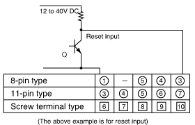
- 2.The input mode and output mode change depending on the DIP switch settings. Therefore, before making any connections, be sure to confirm the operation mode and operation conditions currently set.
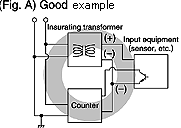
- 3.LC4H series counters use a transformerless power supply system, the input equipments must have the power supply transformer in which the secondary side is not grounded with the primary and secondary sides insulated, in order to prevent interference of the power supply circuit when connecting the external input circuit as Fig. A.
Be sure not to use an autotransformer. In case of secondary side grounded or using the autotransformer, this product may be destroyed due to short circuit electrically as Fig. B (1 and 2).
In case of F.G. terminal of equipments such a PLC grounded in secondary side of the transformer, inner circuits of this product and the input equipment may be destroyed due to short circuit electrically as Fig.B (3).
Therefore, use the isolated type counters or do not ground F.G. terminal of the products.
Once the wiring to be used is completely installed and prior to installing this counter, confirm that there is complete insulation between the wires connected to the power terminals (2 each) and the wires connected to each input terminal. If the power and input lines are not insulated, a short-circuit may occur inside the counter and result in internal damage.
In addition, when moving your equipment to a new installation location, confirm that there is no difference in environmental conditions as compared to the previous location.
(except LC4H-S/AC type)

- 4. The input signal is applied by the shorting of each input terminal with the common terminal (terminal (1) for 8-pin types, terminal (3) for 11-pin types and terminal [6] for screw-down terminal types). Never connect other terminals or voltages higher than DC 40 V, because it may destroy the internal devices.
- 5.Transistor output
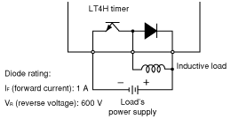
- 1.Since the transistor output is insulated from the internal circuit by a photocoupler, it can be used as an NPN output or PNP (equal value) output. (The above example is 11-pin type)

- 2.Use the diode connected to the output transistor's collector for absorbing the reverse voltage from induced loads.
- 6.When wiring, use shielded wires or metallic wire tubes, and keep the wire lengths as short as possible.
- 7.For the load of the controlled output, make sure that it is lower than the rated control capacity.
4.Output mode setting
The output mode can be set with the DIP switches on the side of the counter. Make the DIP switch settings before installing the counter on the panel.
5.Conditions of usage
- 1.Avoid locations subject to flammable or corrosive gases, excessive dust, oil, vibrations, or excessive shocks.
- 2.Since the cover of the unit is made of polycarbonate resin, avoid contact with or use in environments containing methyl alcohol, benzene, thinners, and other organic solvents; and ammonia, caustic sodas, and other alkaline substances.
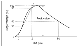
- 3.If power supply surges exceed the values given below, the internal circuits may become damaged. Be sure to use surge absorbing element to prevent this from happening.
| Operating voltage | Surge voltage(peak value) |
|---|---|
| AC type | 6,000V |
| DC type 24V AC type | 1,000V |
Surge wave form
[± (1.2×50) μs uni-polar full wave voltage]
- 4.Regarding external noise, the values below are considered the noise-resistant voltages. If voltages rise above these values, malfunctions or damage to the internal circuitry may result, so take the necessary precautions.
| Power supply terminals | Input terminals | ||
|---|---|---|---|
| AC type | DC type 24V AC type | ||
| Noise voltage | 1,500V | 1,000V | 600V |
Noise wave form (noise simulator)
Rise time : 1ns Pulse width : 1μs,50ns Polarity : ± Cycle : 100 cycles/second- 5.When connecting the operation power supply, make sure that no leakage current enters the counter. For example, when performing contact protection, if set up like that of diagram A, leaking current will pass through C and R, enter the unit, and cause incorrect operation. Diagram B shows the correct setup.

- 6.Long periods of continuous operation in the count-up completed condition (one month or more) will result in the weakening of the internal electrical components from the generated heat and, therefore, should be avoided. If you do plan to use the unit for such continuous operation, use in conjunction with a relay as shown in the circuit in the diagram below.
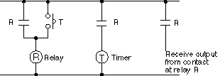
6.Self-diagnosis functions
If a malfunction occurs, one of the following displays will appear.
| Display | Contents | Output condition | Restoration procedure | Preset values after restoration |
|---|---|---|---|---|
or
| Minimum value went below –999 or –99999. See note 1. | No change | Enter reset or RESET key. | No change |
| Incorrect DIP switch setting. | Restart unit (correct DIP switch settings) | ||
| Malfunctioning CPU. | OFF | Enter reset, RESET key, or restart unit. | The values at start-up before the CPU malfunction occurred. |
| Malfunctioning memory. See note 2. | 0 |
Note 1:
When the counter value goes below the minimum value during any of the subtraction, directive, independent, or phase input modes.
Note 2:
Includes the possibility that the EEPROM’s life has expired.
7.Compliance with the CE marking
When using in applications to which EN61812-1 applies, abide by the following conditions.
Overvoltage category II, pollution level 2
(for sensor type model with power supply)
- 1.This counter employs a power supply without a transformer, so the power and input signal terminals are not insulated.
- 1.When a sensor is connected to the input circuit, install double insulation on the sensor side.
- 2.In the case of contact input, use dualinsulated relays, etc.
- The load connected to the output contact should have basic insulation. This counter is protected with basic insulation and can be double-insulated to meet EN/IEC requirements by using basic insulation on the load.
- Applied voltage should be protected with an overcurrent protection device (example: 250 V 1A fuse, etc.) that conforms to the EN/IEC standards.
- 2.You must use a terminal block or socket for installing the pin-type counter. Do not touch the terminal section or other parts of the timer unit while an electric current is applied. Before installation or removal, confirm that there is no voltage being applied to any of the terminals.
- 3.Do not use this timer with a safety circuit. For example, when using a timer in a heater circuit, etc., provide a protection circuit on the machine side.
Installation methods
1.Surface mount
- 1.For the counters of LC4H series, use the pin type counter.

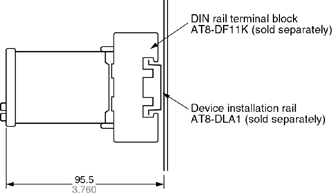
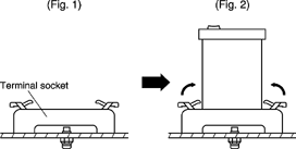
- 2.Put the terminal socket on the board directly or put it on the DIN rail (Fig. 1).
- 3.Insert the counter into the terminal socket and fix it with clip (Fig. 2)
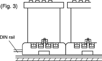
- 4.On DIN rail mounting, mount the counter on the DIN rail tightly to get the proper dimension (Fig. 3).
- 5.8-pin type should be connected with terminal socket AT8-DF8K. 11-pin type should be connected with terminal socket AT8-DF11K.
- 6.DIN rail (AT8-DLA1) is also available (1 m).
2.Flush mount
- 1.For the counters of LC4H series, it is recommended to use the built-in screw terminal type for flush mount. (Mounting frame and rubber gasket are provided when counter is shipped.)

- 2.How to mount the counter
From the panel front, pass the counter through the square hole. Fit the mounting frame from the rear, and then push it in so that the clearance between the mounting frame and the panel surface is minimized. In addition, lock the mounting frame with a screw.
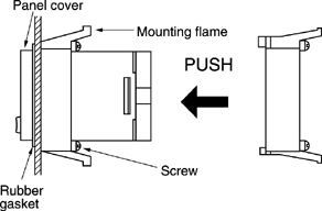
- 3.Caution in mounting the counter
- 1.If the LC4H series are used as the waterproof types (IEC IP66), tighten the reinforcing screws on the mounting frames so that the counters, the rubber gaskets, and the panel surfaces are tightly contacted with each other. (Tighten the two screws with uniform force and make sure that there is no rattling. If the screws are tightened too excessively, the mounting frame may come off.)
- 2.If the counter is installed with the panel cover and the rubber gasket removed, the waterproofing characteristic is lost.
- 4.Removal
Loosen the screws on the mounting frame, spread the edge of frame and remove it.

Pull the mounting frame backward while spreading out its hooks with your thumbs and index fingers

- 5.Correctly connect the terminals while seeing the terminal layout and wiring diagram.
- 6.If the pin type is used, the rear pinbracket (AT8-RR) or the 8P cap (AD8-RC) is necessary to connect the pins. For the 11-pin type, use the 11P cap (AT8-DP11) and avoid directly soldering the round pins on the counter.
- 7.Panel cutout dimensions

The standard panel cutout dimensions areshown in the left figure.(Panel thickness: 1 to 5 mm .039 to .197inch)
- 8.Although the counters can be mounted adjacent to each other in this case, it is recommended to arrange the mounting holes as shown in the figure to facilitate attaching and detaching the mounting frame.
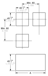
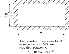
- 9.Adjacent mounting
Although the counters can be mounted adjacent to each other, remember that the panel surface of LC4H series counter will lose its water-resistant effect. (Panel thickness: 1 to 5 mm .039 to .197 inch)
A=(48×n-2.5)+0.60
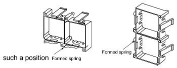
When lining up the counters horizontally, set the frames in such a position so the formed spring areas are at the top and bottom.
When lining up the counters vertically, set the frames in such a position as the formed spring areas are at the right and left.
使用上のご注意
カウンタ使用上のご注意(共通)
商品個別の注意事項は、各商品の「使用上のご注意」をご覧ください。
安全上のご注意 ケガや事故防止のため、以下のことを必ずお守りください。
据付、運転、保守、点検の前に、必ず取り扱い説明書や下記の使用上のご注意をお読みいただき、正しくご使用ください。
機器の知識、安全の情報、そして注意事項のすべてを習熟してからご使用ください。
[警告]取り扱いを誤った場合に、使用者が死亡または重傷を負う危険性が想定される場合
[注意]取り扱いを誤った場合に、使用者が傷害を負うかまたは物的損害のみが発生する危険性が想定される場合
警告
- 本製品の故障や外部要因による異常が発生しても、システム全体が安全側に働くように本製品の外部で安全対策を行ってください。
- 燃焼性ガスの雰囲気では使用しないでください。爆発の原因となります。
- 本製品を火中に投棄しないでください。電池や電子部品などが破裂する原因となります。
注意
- 異常発熱や発煙を防止するため、本製品の保証特性・性能の数値に対し余裕をもたせて使用してください。
- 分解、改造はしないでください。異常発熱や発煙の原因となります。
- 通電中は端子に触れないでください。感電の恐れがあります。
- 非常停止、インターロック回路は外部で構成してください。
- 電線やコネクタは確実に接続してください。接続不十分な場合は、異常発熱や発煙の原因となります。
- はんだ付けは確実に行ってください。不十分な場合は、異常発熱や発煙の原因となります。
- 製品内部に液体、可燃物、金属などの異物を入れないでください。異常発熱や発煙の原因となります。
- 電源を入れた状態では施工(接続、取り外しなど)しないでください。感電のおそれがあります。
回路上のご注意
1.カウンタ接点の保護回路
誘導負荷開閉の回路では、開閉時の逆起電圧(サージ)や突入電流(インラッシュ)により、接点の接触障害が発生する場合があります。したがって、接点保護のために下図のような保護回路の挿入をおすすめします。
| CR方式 | |||
|---|---|---|---|
| 回路例 |  |  | |
| 適用 | AC | △※ | ○ |
| DC | ○ | ○ | |
| 適用上の注意 | 負荷がリレー、ソレノイドなどの場合は復帰時間が遅れます。 電源電圧が24V、48Vの場合は負荷間に、100~200Vの場合は接点間のそれぞれに接続すると効果的です。 | ||
| 負荷がカウンタの場合c、rを通して漏れ電流が流れ込み誤動作を起こすことがあります。 ※AC電圧で使用する場合、負荷のインピーダンスがc、rのインピーダンスより十分小さいこと。 | - | ||
| 素子の選択 | c、rの目安としては c:接点電流1Aに対し0.5~1(μF) r:接点電圧1Vに対し0.5~1(Ω)です。負荷の性質やカウンタ特性のバラツキなどより必ずしも一致しません。 cは接点開離時の放電抑制効果を受けもち、rは次回投入時の電流制限の役割ということを考慮し、実験してご確認ください。 cの耐圧は一般に200~300Vのものを使用してください。AC回路の場合はAC用コンデンサ(極性なし)をご使用ください。 | ||
| ダイオード方式 | バリスタ方式 | ||
|---|---|---|---|
| 回路例 |  |  | |
| 適用 | AC | × | ○ |
| DC | ○ | ○ | |
| 適用上の注意 | コイルに貯えられたエネルギーを並列ダイオードによって、電流の形でコイルへ流し、誘導負荷の抵抗分でジュール熱として消費させます。この方式はcr方式よりもさらに復帰時間が遅れます。 (カタログの復帰時間の2~5倍) | バリスタの定電圧特性を利用して、接点間にあまり高い電圧が加わらないようにする方式です。この方式も復帰時間が多少遅れます。 | |
| 素子の選択 | ダイオードは逆耐電圧が回路電圧の10倍以上のもので順方向電流は負荷電流以上のものをご使用ください。 電子回路では回路電圧がそれほど高くない場合、電源電圧の2~3倍程度の逆耐電圧のものでも使用可能です。 | - | |
2.負荷の種類と突入電流について
負荷の種類とその突入電流特性は、開閉頻度とも関連して、接点溶着を起こす大きな要因です。特に突入電流の存在する負荷の値には定常電流と共に突入電流値を測定し、選定するカウンタとの余裕度を検討しておいてください。下表は代表的な負荷と突入電流との関係を示したものです。
| 負荷の種類 | 突入電流 |
|---|---|
| 抵抗負荷 | 定常電流の1倍 |
| ソレノイド負荷 | 定常電流の10~20倍 |
| モータ負荷 | 定常電流の5~10倍 |
| 白熱電球負荷 | 定常電流の10~15倍 |
| 水銀灯負荷 | 定常電流の1~3倍 |
| ナトリウム灯負荷 | 定常電流の1~3倍 |
| コンデンサ負荷 | 定常電流の20~40倍 |
| トランス負荷 | 定常電流の5~15倍 |
大負荷で、かつ長寿命を期待する場合は、カウンタで直接負荷を制御することは避け、リレーもしくはマグネットスイッチを介した設計をすることにより、カウンタの長寿命化を達成することができます。
3.入力の接続について(LC4H-S/ACタイプ除く)
LC4Hシリーズの電源回路は、トランスレス方式(電源端子と入力端子は絶縁されていない)になっていますので、各種信号入力の接続に際し、短絡防止のためにセンサ等入力機器の電源は、図Aのように1次と2次の絶縁された電源トランスを使用し、しかも2次側が接地されていないものをご使用ください。また、トランスの2次側でPLC等機器のF.G.ラインを接地される場合、電源などの他のラインとF.G.ラインが絶縁されていない機器があるため、図B[(3)]のように短絡状態になり商品の内部回路および入力機器が破壊しますのでご注意ください。この場合、F.G.ラインを接地せずにご使用、または絶縁タイプのタイマをご使用ください。
単巻トランス(スライダック等)をお使いになると、図Bのように短絡状態になり、カウンタ内部回路が破壊しますので使用しないでください。


4.連続通電について
カウントアップ状態で、長時間(約1ヵ月以上)連続通電しますと、内部発熱により電子部品が劣化しますので、連続して通電することは避けてください。もし、連続通電される場合はリレーと組み合わせて、下記の回路にてご使用ください。

5.漏れ電流について
- 操作電源を接続する場合、カウンタに漏れ電流が流れ込まないようにしてください。有接点のみで入切する場合は問題ありませんが、図Aのように接点保護を行う場合、C、Rを通して漏れ電流が流れ込み、誤動作を起こすことがありますので、C、Rで接点保護する場合は、図Bの結線をしてください。
- また、無接点素子で直接カウンタを入切されますと、カウンタに漏れ電流が流れ込み、誤動作することがありますのでご注意ください。

6.端子結線について
端子結線は端子配列・結線図を参照の上、間違いなく確実に行ってください。特にDCタイプは有極ですから逆極性では動作しません。なお、誤結線は誤動作・異常発熱・発火などの原因となりますのでご注意ください。端子金具はY端子を推奨します。(ネジ端子タイプ)
7.操作電源の接続について
- 電源電圧は、スイッチ、リレーなどの接点を介して一気に印加するようにしてください。
- DCタイプの操作電圧は、規定のリップル率以下としてください。また、平均電圧が許容操作電圧範囲内となるようにしてください。
代表的な簡易電源とリップル率を以下に示します。
整流方式 リップル率 単相全波 約48% 三相全波 約4% 三相半波 約17% - 電源スイッチOFFの後、カウンタ電源端子間に誘導電圧・残留電圧が加わらないようにご注意ください。(電源線を高圧線、動力線との平行配線しますと電源端子間に誘導電圧が発生する場合があります。)
8.制御出力について
- 制御出力の負荷は、定格制御容量に示す負荷容量以下でご使用ください。定格以上の値で使用しますと、寿命が著しく短くなりますのでご注意ください。またトランジスタ出力タイプの場合は、トランジスタ破壊の原因になります。
9.取り付けについて
- 取り付けは、専用端子台またはソケット(キャップ)を使用し、カウンタ本体の端子(ピン)に直接はんだ付けをして接続することは避けてください。
- 特性を維持するため、本体カバー(ケース)は外さないでください。
10.電源重畳サージについて
電源重畳サージに対しては、標準波形(±1.2×50μs)にて、耐サージ電圧の規格値としています。(電源端子間へ正負各5回または3回印加)
なお、LC4Hシリーズの規格値については、個別の“使用上のご注意”項をご参照ください。
サージ波形[±(1.2×50)μsの単極性全波電圧]

規格値以上の外来サージが発生する場合は、内部回路が破壊することがありますのでサージ吸収素子をご使用ください。サージ吸収素子にはバリスタ、コンデンサ、ダイオードなどがあります。ご使用の際には、規格値以上の外来サージが発生していないかオシロスコープでご確認ください。
11.信号入力について
カウンタの信号入力は、入力端子を短絡・開放して信号入力する方法と、入力端子間に「H」「L」所定レベルの電圧を与えて信号入力する方法があります。
入力用センサーなどの残留電圧、入力インピーダンス、入力電圧レベルなど信号入力の条件については、各商品ごとに記載されている定格範囲内でご使用ください。
12.使用環境について
- 使用周囲温度や周囲湿度については、各商品ごとに記載された定格範囲内でご使用ください。
- 引火性ガス、腐食性ガスの発生するところ、ゴミやホコリの多いところ、水・油がかかるところ、振動・衝撃の激しいところでのご使用は、お避けください。
- 本体カバー(ケース)、文字板などはポリカーボネート樹脂製ですから、メチルアルコール、ベンジン、シンナーなどの有機溶剤や苛性ソーダなどの強酸性物質、アンモニアなどの付着やそれらの雰囲気でのご使用は避けてください。
- ノイズの多く発生する環境下でカウンタをご使用になる場合、ノイズ発生源、ノイズがのった強電線から、入力信号機器(センサなど)、入力信号線の配線およびカウンタ本体をできるだけ離してください。

13.実負荷確認のお願い
実際に使用するに当たっての信頼性を高めるため、実使用状態での品質確認をお願いいたします。
14.その他
- 定格(操作電圧、制御容量)、接点寿命、電気的寿命など仕様範囲を超えてご使用の場合、異常発熱・発煙・発火の恐れもありますのでご注意ください。
- LC2Hシリーズとエコカウントメータのカウンタには、リチウム電池を内蔵しています。内蔵リチウム電池の分解・火中への投入は、人体・設備に損傷を与える恐れがありますので絶対しないでください。廃棄時には古電池と同じように、不燃物処理の扱いとしてください。
- 万一、本品の不具合が原因となり、人命並びに財産に影響を与えることが予測される場合には、定格・性能の数値に対して余裕を持たれ、かつ二重回路などの安全対策を組み込んでいただくことを製造物責任の観点からもおすすめします。
LC4Hシリーズ使用上のご注意
1.端子結線について
- 端子結線は端子配列・結線図を参照の上、間違いなく確実に行ってください。
- 埋込取付としてご使用の場合、ネジ締め端子タイプをおすすめします。
8ピンタイプは裏面端子台(AT78041)または8Pキャップ(AD8013)、11ピンタイプは裏面端子台(AT78051)または11Pキャップ(ATA4861)を使用し、本体の丸ピンに直接はんだ付けをして接続することは避けてください。
表面取付としてご使用の場合、8ピンタイプはDINレール端子台(ATC180031)、11ピンタイプはDINレール端子台(ATC180041)をご使用ください。 - 操作電源OFF後は、電源端子(2)-(7)(8ピンタイプ)、(2)-(10)(11ピンタイプ)、[1]-[2](ネジ締め端子タイプ)に誘導電圧、残留電圧が加わらないようにご注意ください。(電源線を高圧線、動力線と平行配線すると、電源端子間に誘導電圧が発生する場合があります。)
- 電源電圧はスイッチ、リレーなどの接点を介して一気に印加するようにしてください。徐々に電源を印加しますと設定に関係なくカウントアップすることがあります。
2.入力の接続について(除くLC4H-S/ACタイプ)
電源回路はトランスレス方式(電源端子と入力端子は絶縁されていない)のため、1つの入力信号を複数のカウンタに同時入力される場合は、電源操作を独立させないでください。
図Aのようにカウンタの電源操作が独立した場合は、カウンタ内部回路の破損原因になりますので、絶対にしないでください。(図A、図B、図Cは11ピンタイプの例です。)

電源操作が独立した場合は、図Bのように入力接点またはトランジスタを別々にしてください。

電源操作が独立していない場合は、図Cのように1つの入力信号を複数のカウンタに同時入力することができます。

3.入力・出力について
- 信号入力について
- 有接点入力の場合
接触信頼性のよい金めっき接点のものをご使用ください。接点バウンス時間はカウント値の誤差になるため、バウンス時間の短いものをご使用ください。この場合入力1、入力2は最高計数速度は30Hz、リセットの最小入力信号幅は20msを選択ください。

- 無接点入力の場合
オープンコレクタで接続してください。使用するトランジスタの特性としては、
VCEO=20V以上
IC=20mA以上
ICBO=6μA以下
のものをご使用ください。
また、トランジスタON時の残留電圧は2V以下のものをご使用ください。
※短絡時インピーダンスは1kΩ以下としてください。
0Ω時、流出電流は入力1、入力2端子は約12mA、リセット入力、ロック入力端子は約1.5mA
また、開放時インピーダンスは100kΩ以上としてください。※電源電圧DC12~40Vの範囲の無接点回路(近接スイッチ、光電スイッチなど)からは、下図のようにオープンコレクタのトランジスタ以外でも信号を入力することができます。下図のような場合、無接点トランジスタQがOFFからONになるとき、すなわち信号電圧がHighレベルからLowレベルになるとき、入力されます。

- 有接点入力の場合
- 入力モードと出力モードは、ディップスイッチの設定によって変わりますので、接続の前に設定した動作モードと動作状態とをご確認ください。
- 本機種は、トランスレス電源方式(AC電源入力部と入力機器入力部は非絶縁)になっていますので、各種信号入力の接続に際し、短絡防止のためにセンサ等入力機器の電源は、図Aのように1次、2次の絶縁された電源トランスを使用し、しかも、2次側が接地されていない物をご使用ください。
2次側が接地された状態、または単巻きトランス(スライダック等)を使用された場合は、図B [(1),(2)]のように短絡状態となり、商品の内部回路が破壊しますのでご注意ください。
また、トランスの2次側でPLC等機器のF.G.ラインを接地される場合、電源などの他のラインとF.G.ラインが絶縁されていない機器があるため、図B [(3)]のように短絡状態になり商品の内部回路および入力機器が破壊しますのでご注意ください。
この場合、F.G.ラインを接地せずにご使用、または絶縁タイプのカウンタをご使用ください。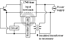

- 入力信号は、それぞれの入力端子と共通端子(8ピンタイプは端子(1)、11ピンタイプは端子(3)、ネジ締め端子タイプは端子[6])を短絡することで印加されます。ほかの端子と接続したり、電圧をDC40V以上印加したりすると、内部回路を破壊しますので絶対にしないでください。
- トランジスタ出力について
- トランジスタ出力はフォトカプラにて内部回路と絶縁されていますのでNPN出力、PNP(等価)出力のどちらにもお使いいただけます。(下図は11ピンタイプの例です。)

- 出力トランジスタのコレクタに接続してあるダイオードは、誘導負荷使用時の逆起電圧吸収用としてご利用ください。
(LC4Hのみ)
- トランジスタ出力はフォトカプラにて内部回路と絶縁されていますのでNPN出力、PNP(等価)出力のどちらにもお使いいただけます。(下図は11ピンタイプの例です。)
- 配線はシールド線、または単独に金属電線管を使用してできるだけ短く行ってください。
- 制御出力の負荷は、必ず定格制御容量以下でご使用ください。
4.出力モードの設定
出力モードの設定は、カウンタ側面の[ディップスイッチ部]で設定ができます。ディップスイッチの設定は、カウンタの盤面取り付け前に行ってください。
5.使用条件について
- 引火性ガス、腐食性ガスの発生するところや、塵埃の多いところ、油のかかるところ、振動、衝撃の激しいところでのご使用は避けてください。
- 本体カバーはポリカーボネート樹脂製ですから、メチルアルコール、ベンジン、シンナーなどの有機溶剤や、アンモニア、苛性ソーダなど、強アルカリ性物質の付着やそれらの雰囲気でのご使用は避けてください。
- 電源重畳サージが次の値を超えると、内部回路が破壊することがあるため、サージ吸収素子をご使用ください。
操作電圧 サージ電圧(波高値) ACタイプ 6,000V DCタイプ AC24Vタイプ 1,000V サージ波形[±(1.2×50)μsの単極性全波電圧]

- 外部ノイズに対しては、下記の値を耐ノイズ電圧としていますが、これ以上になりますと誤動作、内部回路破壊の原因となりますのでご注意ください。
電源端子間 入力端子間 ACタイプ DCタイプ AC24Vタイプ ノイズ電圧 1,500V 1,000V 600V ノイズ波形(ノイズシミュレータ)
- 立上り:
1ns - パルス幅:
1μs,50ns - 極性:
± - 周期:
100回/秒
- 立上り:
- 操作電圧を接続する場合、カウンタに漏れ電流が流れ込まないようにしてください。有接点のみで入切する場合は問題ありませんが、図Aのように接点保護を行う場合、C,Rを通して漏れ電流が流れ込み、誤動作を起こすことがありますので、図Bの結線をしてください。

- カウントアップ状態で、長時間(約1ケ月以上)連続通電しますと、内部発熱により電子部品が劣化しますので、連続して通電することは避けてください。もし、連続して通電される場合はリレーと組み合わせて、下記の回路にてご使用ください。

6.自己診断機能について
異常が発生したとき、下記の表示になります。
| 表示 | 内容 | 出力状態 | 復帰方法 | 復帰後のプリセット値 |
|---|---|---|---|---|
    または       | 最小値-999または-99999を下回ったとき ※1 | 変化なし | [RESET]キーまたはリセット入力 | 変化なし |
 | ディップスイッチ設定異常 | 電源再投入(ディップスイッチ設定変更のこと) | ||
 | CPU異常 | OFF | [RESET]キー入力、リセット入力または電源再投入 | CPU異常直前の電源投入時の設定値 |
 | メモリ異常 ※2 | 0 |
※1.減算、指令、個別、位相差モードにおいて、計数値が最小値を下回ったとき発生。
※2.EEP-ROMの書き換え寿命に達した場合も含む。
7.CEマーキング対応について
EN61812-1に適合させる用途にご使用の場合には、以下の条件にてご使用ください。
過電圧カテゴリーIII、汚染度2
(センサ用電源付タイプ)
- 電源、入力出力相互間は基礎絶縁となっています。入出力端子接続する機器は基礎絶縁されたものを使用してください。
(センサ用電源なしタイプ)
- 本カウンタは、電源トランスレス方式を採用しており、電源端子と入力信号端子は絶縁されていません。
- センサを入力回路に接続する場合は、センサ側に2重絶縁を設けてください
- 有接点入力の場合は、2重絶縁されたリレーなどを使用してください。
- 出力接点に接続される負荷は、基礎絶縁されたものを接続してください。本カウンタは、基礎絶縁を確保しており負荷の基礎絶縁と合わせて、EN/IECで要求される2重絶縁が確保できます。
- 印加される電源はEN/IEC規格に適合した過電流保護装置(例えば250V 1AのFuseなど)により保護されているものにしてください。
- ピンタイプ取り付けは、必ず端子台、またはソケットをご使用ください。通電中は、端子部などタイマ本体に触れないでください。取り付け・取り外しの際は、すべての端子に電圧が印加されていないことを確認してください。
- 本タイマを安全回路に使用しないでください。例えば、ヒータ回路などにタイマを使用する場合は、機械側に保護回路を設けてください。
施工方法
1.表面取り付けの場合


- 端子台は、DINレール端子台8ピンタイプは(ATC180031)、11ピンタイプは(ATC180041)をご使用ください。
- 機器取付レールは、ATA48011(1m)をご使用ください。
2.埋込取り付けの場合
- カウンタは、埋込専用カウンタのネジ締め端子タイプをおすすめいたします(取付枠、ゴムパッキンは、同梱されております)。

取り付け方法について
本体をパネル前面から角穴へ入れ、裏面から取付枠を挿入し、パネル面とのすき間が少なくなるよう押し込んでください。ネジ(2ヶ所)を均等に締め付けて、ガタツキのないことを確認してください。締め付けすぎますと枠がはずれます。そのときはネジをもどし、枠を押し込んでから締めなおしてください。

- 取付時のご注意
- 防水タイプとしてご使用の場合、操作部は防水構造(IEC規格IP66)となっていますがカウンタ本体とゴムパッキン、パネル面が充分密着されている様、取付枠の補強ねじを締めつけてご使用ください。(ネジ2ヶ所を均等に締め付けてガタツキのないことを確認してください。締め付け過ぎますと枠がはずれることがあります)
- パネルカバーおよびゴムパッキンをはずしての取付は、パネル面の防水性が失われますのでご注意ください。
- 取りはずし方法について
取付枠のねじをゆるめてフックを外側へ押し広げて取付枠をはずしてください。
両手の親指と人さし指でフックを外側へ押し広げながら後方に取付枠を引いてください。

- 端子結線は端子配列結線図を参照の上、間違いなく確実に行ってください。
また端子ネジの絞め付けトルクは0.8N・cm以下としてください。(ネジ締め端子タイプ) - ピンタイプをご使用の場合、端子接続には8ピンタイプは、裏面端子台(AT78041)または8Pキャップ(AD8013)、11ピンタイプは裏面端子台(AT78051)または11Pキャップ(ATA4861)を使用し、本体の丸ピンに直接はんだ付けをして接続することは、避けてください。
- パネルカット寸法について

標準パネルカット寸法は図に示すとおりです。(パネル厚:1~5mm)
- 埋込取付は、連続取付が可能ですが、取付枠の着脱が行いやすくなるため下図の寸法で穴加工することをおすすめします。

連続取付について
連続取付ができますが、この場合、パネル面の防水性が失われますのでご注意ください。(パネル厚:1~5mm)
n個連続取付の場合のAの目安寸法は、
本体をヨコに連続取付をする場合取付枠の成形ばね部が上下になるようにセットしてください。
本体をタテに連続取付をする場合取付枠の成形ばね部が左右になるようにセットしてください。
------------------------------ Tab5 showing ------------------------------
Wiring/ Connection
Terminal Layout and Wiring
Pin type
Relay output type

Screw-down terminal type
Relay output type

* For connecting the output leads of the transistor output type, refer to 5) TRANSISTOR OUTPUT.
