The rated switching power and life mentioned in the specification and catalog are given only as guides.
A relay may encounter a variety of ambient conditions during actual use resulting in unexpected failure.
Therefore, it is necessary for proper use of the relay to test and review with actual load and actual application under actual operating conditions.
Use that exceeds the specification ranges such as the coil rating, contact rating and switching life should be absolutely avoided. Doing so may lead to abnormal heating, smoke, and fire.
Never touch live parts when power is applied to the relay. Doing so may cause electrical shock. When installing, maintaining, or troubleshooting a relay (including connecting parts such as terminals and sockets), be sure that the power is turned off.
When connecting terminals, please follow the internal connection diagrams in the catalog to ensure that connections are done correctly. Be warned that an incorrect connection may lead to unexpected operation error, abnormal heating, and fire.
If there is a possibility that adhesion, contact failure, or breaking of wire could endanger assets or human life, please make sure that a fail-safe system is equipped in the vehicle.
In order to use the relays properly, the characteristics of the selected relay should be well known, and the conditions of use of the relay should be investigated to determine whether they are matched to the environmental conditions, and at the same time, the coil specification, contact specification, and the ambient conditions for the relay that is actually used must be fully understood in advance.
In the table below, please refer to a summary of the consideration points regarding selection of relay.
Items | Consideration points regarding selection | |
---|---|---|
Coil | a) Rating b) Operate voltage (current) c) Release voltage (current) d) Maximum applied voltage (current) e) Coil resistance f) Temperature rise | - Select relay with consideration for power source ripple. - Give sufficient consideration to ambient temperature and for the coil temperature rise, and hot start. - When used in conjunction with semiconductors,careful with the voltage drop. - When starting up, careful with the voltage drop. |
Contact | a) Contact arrangement b) Contact rating c) Contact material d) Life e) Contact resistance | - Note that the relay expected life is balanced with the life of the device the relay is used in. - Is the contact material matched to the type of load? It is necessary to take care particularly with low level usage. - The rated life may become reduced when used at high temperatures. Life should be verified in the actual use atmosphere. - It is necessary to be tested and reviewed under actual use conditions with actual load and actual application. |
Operate time | a) Operate time b) Release time c) Bounce time d) Switching frequency | - Note that ambient temperature and applied voltage cause the change of operate time and bounce time. - Note that operate time and release time do not include bounce time. - Give consideration that switching life changes depending on switching frequency. |
Mechanical characteristics | a) Vibration resistance b) Shock resistance c) Ambient use temperature d) Life | - Give consideration to performance under vibration and shock in the use location. - Confirm the allowable ambient temperature of the relay. |
Other items | a) Dielectric strength b) Mounting, Connection c) Size d) Protection construction | - Selection can be made for connection method with plug-in type, printed circuit board type, soldering, and screw fastening type. - Selection of protection construction can be made for PC board mounting method such as soldering and cleaning. - For use in an adverse atmosphere, sealed construction type should be selected. In some environments, the sealing performance may fail. Therefore, it is necessary to confirm device performance in actual atmosphere. - Are there any special conditions? |
Contact performance is significantly influenced by voltage and current values applied to the contacts (in particular, the voltage and current waveforms at the time of application and release), the type of load, frequency of switching, ambient atmosphere, contact switching speed, and of bounce, which lead the various other damages such as unsuitable operation contact transfer, welding, abnormal wear, increase in contact resistance. Therefore, please confirm that in actual use conditions such as actual circuit and actual load. Also, note that the automotive relay cannot be applied AC load.
In the case of switching on and off with inductive loads such as coil, magnet crutch, and solenoid, the arc at switching can cause a severe damage on contacts and greatly shortening of life. In addition, in the case of switching at a high frequency, a blue-green corrosion may be developed. So, please contact our company to use it.
If the current in the inductive load is relatively small, the arc discharge decomposes organic matter contained in the air and causes black deposits (oxides, carbides) to develop on the contacts. This may result in contact failure. So, please contact our company to use it.
Large inrush current enhancing contact welding will be impressed. Its current value is greatly affected by wiring resistance, switching frequency and ambient temperature. The load current characteristics in actual circuit and actual use condition must be examined and sufficient margin of safety must be provided in selection of a relay.
It is dangerous to use a lamp load whose nominal current is small even a large nominal current has been tested beforehand.
Please contact us when switching at nominal current with a small lamp load (40 W or less), because continuous ON failure may occur due to locking caused by contact-transfer phenomenon when switching arc is locally concentrated.
Its load current tends to cause contact welding easily because its inrush current is larger than that of the regular lamp load. The load current characteristics in actual circuit and actual use condition must be examined and sufficient margin of safety must be provided in selection of a relay.
It is necessary to check the contact reliability because the load current of the LED load is very small.
Please contact us before use.
Please inquire our sales representative before use of new structured lamp except for halogen, Electricdischarge lamp, and LED.
When using of N.C. contact side of 1 Form C contact for the motor brake, electrical life might be affected by the brake current. Therefore, verify in actual use conditions with actual circuit.
The larger inductivity of motor may cause contact damage and transfer even the motor load current is same. Therefore, verify in actual use conditions with actual circuit.
Note that its load current tends to cause contact welding and contact transfer easily because its inrush current is generally large which has a small break current and a short time period to reach an inrush peak value.
Also, inrush current value is influenced by wiring resistance. Therefore, the inrush current in actual circuit must be examined and sufficient margin of safety must be provided in selection of a relay.
This load causes relatively-less contact damage since its inrush current is not large. Select a relay based on the rating control capacity.
Electrical life may be affected by load polarity (+/-) connecting to relay contacts. So, please verify them in actual use polarity.
Under a circuit which inrush current is applied to such as lamps and capacitors, the moment the contact is closed, voltage drop to the coil, return of relay, or chattering may occur. Note that it may remarkably reduce the electrical life.
If the load voltage is high, the arc energy which generated at contact switching increases, which may decrease the electrical life. Therefore, it is necessary to give consideration to the voltage which could occur in actual use condition.
If coil applied voltage gets higher, the relay operate time gets faster. However, contact bounce gets also larger so that the electrical life may decrease.
When the short-pulse signal is input to the relay coil, the relay movable part may operate and touch lightly to the contact. Therefore, please avoid short pulse input (100 ms or less) since it may cause contact welding due to less contact pressure. Please test adequately, for example when a relay is operated by external manual switch (such as key switch.)
When the switching frequency is high, the electrical life may decrease. Please confirm if there is a high-frequent switching caused by abnormal mode in actual use condition.
Note that if the contact has not been switched for a long time period, organic film tends to be generated on the contact surface, which may cause contact instability.
Verify in the actual use condition since electrical life may be affected by use at high temperatures.
If resistor, diode, zener diode are connected parallel to the relay coil and decrease the surge voltage when the relay coil being turned off, the relay release time will get longer and may decrease the electrical life or cause light-welding.
Recommended zener diode
Recommended resistor
Please test a relay in actual vehicle condition since there is a risk of deterioration at relay function or switching performance such as slower release time which is caused by sneak current due to diode, zener diode, capacitor mounted on a vehicle or by remaining current soon after a motor is turned off.
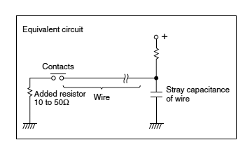
If long wires (a few ten meters) are to be used in a relay contact circuit, inrush current may become a problem due to the stray capacitance existing between wires. In such case, add a resistor in series with the contacts.
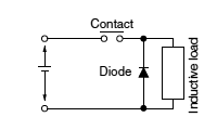
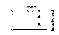
Use of contact protective devices or protection circuits can suppress the counter electromotive force to a low level. However, note that incorrect use will result in an adverse effect. Typical contact protection circuits are given in the table below.
Also, note that release time will slow down due to sneak in the circuit and may cause the electrical life to shorten and slight-welding.
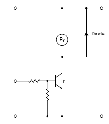
Diode circuit | |
---|---|
Circuit | |
Features/Others | The diode connected in parallel causes the energy stored in the coil to flow to the coil in the form of current and dissipates it as joule heat at the resistance component of the inductive load. This circuit delays the release time. |
Devices Selection | Use a diode with a reverse breakdown voltage at least 10 times the circuit voltage and a forward current at least as large as the load current. In electronic circuits where the circuit voltages are not so high, a diode can be used with a reverse breakdown voltage of about 2 to 3 times the power supply voltage. |
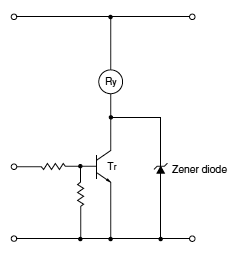
Diode and zener diode circuit | |
---|---|
Circuit | |
Features/Others | It is effective in the diode circuit when the release time is too long. |
Devices Selection | Use a zener diode with a zener voltage about the same as the power supply voltage. |
In the actual circuit, it is necessary to mount the protective device (diode etc.) in the immediate vicinity of the load. If it is mounted too far away, the effectiveness of the protective device may diminish. As a guide, the distance should be within 50 cm.
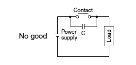
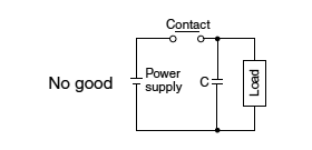
Avoid using the protection circuits shown in the figures below.
Although it is usually more difficult to switch with DC inductive loads compared to resistive loads, use of the proper protection circuit will raise the characteristics to that for resistive loads.
Although it is extremely effective in arc suppression as the contacts open, the contacts are susceptible to welding since energy is stored in C when the contacts open and discharge current flows from C when the contacts close. | Although it is extremely effective in arc suppression as the contacts open, the contacts are susceptible to welding since charging current flows to C when the contacts close. |
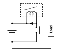
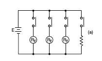
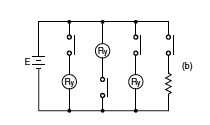
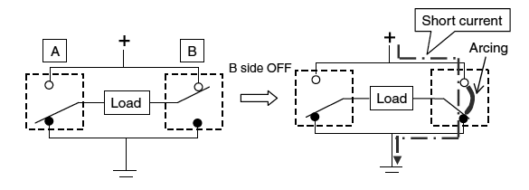
Connect the load to one side of the power supply as shown in Fig. (a). Connect the contacts to the other side. This prevents high voltages from developing between contacts. If contacts are connected to both side of the power supply as shown in Fig. (b), there is a risk of shorting of the power supply when relatively close contacts short.
Fig. (a) Good example | (b) Bad example |
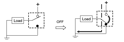
Note that regarding the following circuit constructions with 2-coil relays (twin relays) or single-pole relays, an arc between contacts may be generated when breaking of load current depending on the type of load current, voltage, and load.
<2-coil relay (twin relay) or two of single-pole relays>
<Single-pole relay>
When using of multiple relays such as 2-coil relays (twin relays), verify insulation and breakdown voltage between contacts in each pole in order to avoid an accident caused by short.
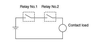
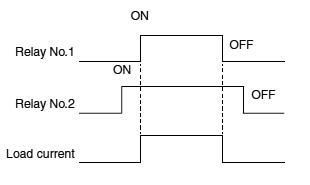
The two relays are connected in series as shown in the right side figure. When each relay is controlled with a different timing chart (shown in the right side figure bottom), the relay No.2 does not flow the load current during operation and release time. This relay No.2 operation is called "Dry-switching".
Dry-switching can reduce the consumption of contact material without current conduction, on the other hand, as the contact cleaning effect disappear, conduction failure may occur.
For the abovementioned reasons, note that our relay application in this dry-switching condition is not recommended in applying our relay.
Timing chart:
After continuous applying of current to coil and contacts, if the current is turned OFF then immediately turned ON again, coil resistance and the pick-up voltage will increase due to the temperature rise in the coil.
Temperature rise value of coil is greatly affected by circuit board, connected harness, connected connector, heat dissipation of system/modules, and heat source around relay. Please verify whether it is operating properly or inoperative under actual vehicle and actual use conditions.
Coil resistance and operate voltage will increase when the relay is used in a higher temperature atmosphere. The resistance/temperature coefficient of copper wire is about 0.4% for 1°C, and the coil resistance increases with this ratio. On the other hand, coil resistance and the release voltage will decrease at lower temperature. Coil resistance change decreases with the same ratio at higher temperature, about 0.4% for 1°C.
Therefore, please confirm the relay operation in used operating temperature range, with attention to such temperature characteristic.
The ambient usage temperature should be set as around the relay inside the box because a heat generated by a relay itself or other instruments causes increase of temperature inside the box.
Note that application of a voltage equal to or greater than the maximum applied voltage may cause a temperature rise that could cause coil burning or a layer short. Please inquire our sales representative regarding PWM control.
For relays which have multiple coils such as twin relay for forward-reverse operation of motor, if the coils are continuously turned on at the same time, the coil temperature may exceed the tolerance in a short time due to heat generation of each coil. Please inquire our sales representative before use.
Coil heating due to continuous current applying to coil for extensive time periods will cause deterioration in insulation performance for coil.
For such circuit types, please consider the fail-safe circuit design in case of contact failure or breaking of coil.
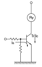
Collector connection method is the most recommendable when the relay is driven by means of a transistor.
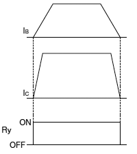
To avoid troubles in use, the rated voltage should always be impressed on the relay in the ON time and zero voltage be done in the OFF time.
(Good) Collector connection | (Care) Emitter connection | (Care) Parallel connection |
If the coil current is suddenly interrupted, a sudden high voltage pulse is developed in the coil. If this voltage exceeds the dielectric strength of the transistor, the transistor will be degraded, and this will lead to damage. It is absolutely necessary to connect a diode in the circuit as a means of preventing damage from the counter emf. In case of DC relay, connection of Diode is effective. As suitable ratings for this diode, the average rectified current should be equivalent to the coil current, and the reverse blocking voltage should be about 3 times the value of the power source voltage. Connection of a diode is an excellent way to prevent voltage surges, but there will be a considerable time delay when the relay is open. Consequently, electrical switching performance of relay may be reduced. If it is need to reduce this time delay, performance will be improved by connecting a Zener diode that is rated for more than double the voltage in the circuit between the transistor's Collector and Emitter.
<Recommended circuit>
Take care of Area of Safe Operation (ASO).
It is necessary for the relay coil not to apply voltage slowly but to apply the rated voltage in a short time and also to drop the voltage to zero in a short time.
Non-pulse signal | Pulse signal | |
(No Good) Without snap action | (Good) Snap action |
When the input signal does not produce a snap action, ordinarily a Schmitt trigger circuit is used to produce safe snap action.
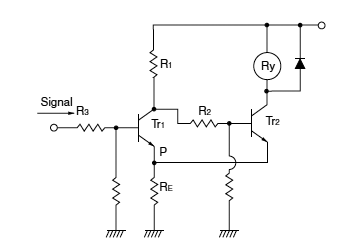
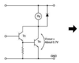
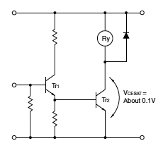
Care must be taken in this circuit due to increase of VCESAT. It does not cause a failure immediately, but it may lead to troubles by using for a long period or by operating with many units.
(No good) Darlington connection | (Good) Emitter connection |
In switching operation where a semiconductor (transistor, UJT, etc.) is connected to the coil, a residual voltage is retained at the relay coil which may cause incomplete restoration and faulty operation. Using of DC coils may cause incomplete restoration or reduction in contact pressure and vibration resistance, because its release voltage is lower than that of AC coil (10% or more of the rated voltage) also because there is a tendency to increase the life by lowering the release voltage.
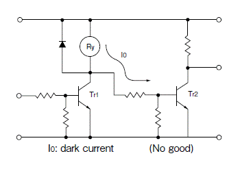
When the signal from the transistor's collector is taken and used to drive another circuit as shown in the figure as follows, a minute dark current flows to the relay even if the transistor is off. This may also cause the problems described above.
Connection to the next stage through collector
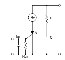
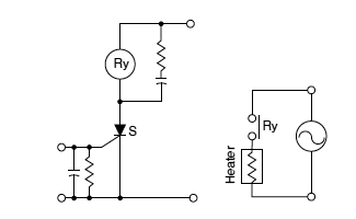
For SCR drive, it is necessary to take particular care with regard to gate sensitivity and erroneous operation due to noise.
IGT : There is no problem even with more than 3 times the rated current.
RGK : 1K ohms must be connected.
RC : This is for prevention of switching error due to a sudden rise in the power source or to noise. (dv/dt measures)
Care must be taken because the electrical life suffers extreme shortening when the relay contacts close simultaneously with an AC single phase power source.
Note that when switching with a very small load after switching with a large load, contact failure by small load switching may occur due to particles generated during switching of the contact with large load.
Note that if it is connected or installed with a high heat-capacity such as bus bar, connector, harness, and PC board, heat removal phenomenon at low temperature will make relay terminals and contacts cool and condensate a small amount of organic gas inside the relay, which may cause a contact failure. So, please inquire our sales representative before use.
Contact resistance consists of dynamic and static contact resistance. Contact resistance on the catalogue and the specifications refers to static contact resistance. Note that dynamic contact resistance usually shows a large value due to just after the contact operation.
Note that if the contact-applied voltage is small (at 6 V or less) and contact-applied current is small (at 1 A or less), contact resistance may become a larger value due to a small amount of film on a contact surface.
Mechanical relays produce an operational noise at operate and release time. Note that if the coil-applied voltage is higher at operate time, the noise becomes larger.
It is necessary to test relays in actual installation condition because operate noise may become larger in the installation condition than with a relay by itself due to resonance and sympathetic vibrations of installation PC board and system module.
Note that if a large current is applied to the contact, electromagnetic repulsion makes contact vibrate and may produce small abnormal noise. Please inquire our sales representative if quietness is required.
Note that if an external vibration and shock are applied to a relay while the relay turns off, a movable part of the relay may vibrate and produce a noise. If quietness is required, after mounting, please test in the actual use condition.
When the relay turns off, surge voltage is generated from the coil. This surge voltage can be reduced if a resistor is connected in parallel to the coil. Likewise, it can be reduced more if a diode instead of resistor is connected in parallel.
However, please note that if a resistor and a diode is connected in parallel electrical life may be affected due to slowing down of release time.
Note)
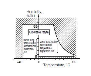
1. The humidity range varies with the temperature. So, use relays within the range indicated in the graph below.
2. If products are air freighted, as long as they are kept in a regular air transportation environment (approx. 80 kPa), product quality will not be affected.
(The allowable temperature range differs for each relay.)
It is recommendable to use relays in a normal temperature and humidity with less dust, sulfur gases (SO2, H2S), and organic gases.
Sealed relays should be considered for applications in an adverse environment.
When a source of silicone gas (silicone rubber, silicone oil, silicone coating materials and silicone filling materials etc.) is used around the relay, the silicone gas (low molecular siloxane etc.) may be produced.
The produced silicone gas may penetrate the plastic case and enter the inside of the relay. When the relay is kept and used in this condition, silicone compound may adhere to the relay contacts. The silicone compound may be changed to the insulator which may cause the contact failure. Do not use any sources of silicone gas around the relay.
If relays are proximately installed each other or installed near highly-magnetized parts such as motor and speaker, the relay may change its operational characteristics or cause malfunction. Therefore, after mounting, check performance in actual operational conditions.
Vibration of the area where relay is installed may be enhanced more than expected depending on installation condition of PC board. So, please verify in actual use condition. N.O. contact is the recommended contact for the use at the vibration-frequent area because the vibration resistance performance of N.C. contact is generally inferior to that of N.O. contact.
In addition, owing to adverse effects on the characteristics of the relay, ensure that devices are not exposed to ultorasonic or high frequency vibrations.
It is ideal for mounting of relay that the movement of the contacts and movable parts is perpendicular to the direction of vibration or shock. Especially note that the vibration and shock resistance of N.C. contacts while the coil is not excited is greatly affected by the mounting direction of the relay.
Water condensation occurs when the ambient temperature drops suddenly from a high temperature and humidity, or, the relay is suddenly transferred from a low ambient temperature to a high temperature and humidity.
Condensation causes the failures like insulation deterioration, wire disconnection and rust etc. Panasonic Industry does not guarantee the failures caused by condensation.
The heat conduction by the equipment may accelerate the cooling of relay itself, and the condensation may occur. Please confirm no condensation in the worst condition of the actual usage.
(Special attention should be paid when high temperature heating parts are close to the relay. Also please consider the condensation may occur inside of the relay.)
Note that if a relay is connected or installed with a high heat-capacity such as bus bar, connector, harness, and PC board, heat removal phenomenon will accelerate cooling of the relay inside and promote condensation. So, please verify in actual installation condition.
Do not use PC board type in environments where wetting may occur.
Since we have different types with various water resistance specifications, please inquire our sales representative.
Please check the icing when an ambient temperature is lower than 0°C. Icing means, the moisture contained in the surrounding environment and inside the relay freezes when the ambient temperature falls below the freezing point. The icing causes the sticking of movable portion, the operation delay and the contact conduction failure etc. Panasonic Industry does not guarantee the failures caused by the icing.
The heat conduction by the equipment may accelerate the cooling of relay itself and the icing may occur.
Icing condition is changed by ambient environment, please make sure to confirm no icing in the worst condition of the actual usage.
Note that if a relay is connected or installed with a high heat-capacity such as bus bar, connector, harness, and PC board, heat removal phenomenon will accelerate cooling of the relay inside and promote freezing. So, please verify in actual installation condition.
The plastic becomes brittle if the relay is exposed to a low temperature, low humidity environment for long periods of time.
Please consider the vibration at installation area to avoid loosely-contact.
Also, note that even a microscopic vibration may cause contact failure at the contact area of relay terminal and connector.
Decrease of fitting performance of connector may cause abnormal heat at connector contact area depending on use temperature and applying heat. Sufficient margin of safety must be provided in selection of a connector.
Please select the proper material of connector and surface treatment to avoid corrosion at the contact area of relay terminal and connector and increase of resistance at connecting area which may be caused depending on ambient environment.
Operating relays may generate noise that can affect electrical circuits. Therefore, the following points should be noted.
(No good)
| (Good)
|
The Hole and Land diameter are made with the hole slightly larger than the lead wire so that the component may be inserted easily. Also, when soldering, the solder will build up in an eyelet condition, increasing the mounting strength. The standard dimensions for the Hole diameter and Land are shown in the table below.
Standard dimensions for the Hole and Land diameter
(Unit: mm)
Standard hole | Tolerance | Land diameter |
---|---|---|
0.8 | ±0.1 | 2.0 to 3.0 |
1.0 | ||
1.2 | 3.5 to 4.5 | |
1.6 |
(Remarks)
Because copper-clad laminates have a longitudinal and lateral direction, the manner of punching fabrication and layout must be observed with care. Expansion and shrinkage in the longitudinal direction due to heat is 1/15 to 1/2 of that in the lateral, and accordingly, after the punching fabrication, the distortion in the longitudinal direction will be 1/15 to 1/2 of that in the lateral direction. The mechanical strength in the longitudinal direction is 10 to 15% greater than that in the lateral direction.
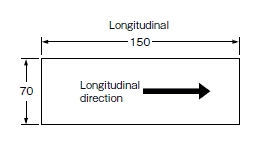
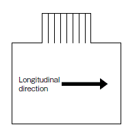
Because of this difference between the longitudinal and lateral directions, when products having long configurations are to be fabricated, the lengthwise direction of the configuration should be made in the longitudinal direction, and PC boards having a connector section should be made with the connector along the longitudinal side. (The figure below)
Example: As shown in the drawing below, the 150 mm direction is taken in the longitudinal direction.
Also, as shown in the drawing below, when the pattern has a connector section, the direction is taken as shown by the arrow in the longitudinal direction.
In keeping with making devices compact, it is becoming more common to solder the relay to a PC board along with the semiconductors instead of using the previous plug-in type in which relays were plugged into sockets.
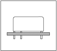
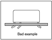
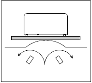
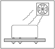
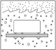
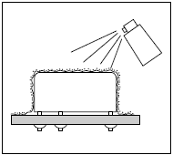
With this style, loss of function may occur because of seepage into the relay of flux, which is applied to the PC board. Therefore, the following precautions are provided for soldering a relay onto a PC board. Please refer to them during installation in order to avoid problems.
The type of protective structure will determine suitability for automatic soldering or automatic cleaning. Therefore, please review the parts on construction and characteristics.
Temperature | 100°C or less (PC board solder surface) |
---|---|
Time | Within 2 minutes |
Note) CB and CM relays are not applicable. Please refer to individual product catalog.
Automatic soldering
Solder temperature | 260°C or less |
---|---|
Soldering time | Within 5 seconds |
Hand soldering
Soldering iron | 30W to 60W |
---|---|
Iron tip temperature | 300°C |
Soldering time | Within 3 seconds |
Note) CB and CM relays are not applicable. Please refer to individual product catalog.
Coating material type | Suitability for relays | Features |
---|---|---|
Epoxy-base | Good |
|
Urethane-base | Care |
|
Silicon-base | No good |
|
Please inquire our sales representative about coating materials other than those listed above. Also please follow individual specification.
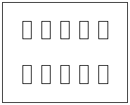
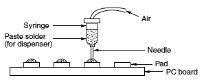
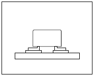
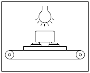
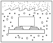
To meet the market demand for downsizing to smaller, lighter, and thinner products, PC boards also need to proceed from insertion mounting to surface mounting technology.
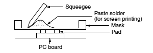
To meet this need, we offer a line of surface mount relays. The following describes some cautions required for surface mount relay installation to prevent malfunction and incorrect operation.
*Please inquire our sales representative for or reflow soldering of through-hole terminal type.
Screen Printing
Solder Dispenser
<Example of recommended soldering condition for surface mount relays>
1. IRS profile
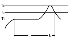
T1 = 150 to 180°C
T2 = 230°C or more
T3 = Less than 250°C
t1 = 60 to 120 sec.
t2 = Less than 30 sec.
Note) Temperature profile indicates the temperature of the soldered part (*1) of terminals on the surface of a circuit board. The exterior temperature of a relay may be extremely high depending on the component density on the board or the heating method of the reflow oven or circuit board type. Sufficient verification under actual processing conditions is required. Performance-guaranteed temperature varies by product. Please refer to the relevant product catalog.
<Others>
For other solder methods except for the above (such as hot air heating, hot plate heating, laser heating, pulse heating, etc.), please check for mounting and soldering condition before use.
It is recommended that the soldered pad be immediately cooled to prevent thermal damage to the relay and its associated components.
Relay's functional damage may occur if strong vibration, shock or heavy weight is applied to a relay during transportation of a device in which a relay is installed. Therefore, please pack them in a way, using shock-absorbing material, so that the allowable range for vibration and shock is not exceeded.
If the relay is stored for extended periods of time (including transportation period) at high temperatures or high humidity levels or in atmospheres with organic gas or sulfide gas, sulfide film or oxide film may be formed on surface of the contacts, which may cause contact instability, contact failure and functional failure. Please check the atmosphere in which the units are to be stored and transported.
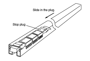
Some types of relays are supplied with tube packaging. If you remove some relays from the tube, be sure to slide a stop plug into one end of a tube to hold the remaining relays firmly and avoid rattling of relay inside the tube. Note that rattling may cause a damage on appearance and/or performance.
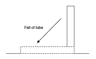
Do not use the relays if they were dropped or fallen down in a tube packing condition because there is a risk of characteristic failure.
If PC boards are processed after relays have been mounted on the board, it is possible that swarf or other foreign matter resulting from machining or other processes may get inside the relays and cause malfunctions or contact failure. Pay particular attention if using flux tight relays or relays with vent hole. In addition, take care to avoid vibrations and shocks during PC board processing that may affect the characteristics and structural integrity of the relay.
In the industrial world, reliability is an index of how long a particular product serves without failure during use period.
Every product has a finite service lifetime. This means that no product can continue normal service infinitely. When a product has broken down, the user may throw it away or repair it. The reliability of repairable products is recognized as "reliability in a broad sense of the term." For repairable products, their serviceability or maintainability is another problem. In addition, reliability of product design is becoming a serious concern for the manufacturing industry. In short, reliability has three senses: i.e. reliability of the product itself, serviceability of the product, and reliability of product design.
Reliability is "built" into products. This is referred to as intrinsic reliability which consists mainly of reliability in the narrow sense. Product reliability at the user's site is called "reliability of use," which consists mainly of reliability in the broad sense. In the relay industry, reliability of use has a significance in aspects of servicing.
The following list contains some of the most popular reliability measures:
Reliability measure | Sample representation |
---|---|
Degree of reliability R(T) | 99.9% |
MTBF | 100 hours |
MTTF | 100 hours |
Failure rate lambda | 20 fit, 1%/hour |
Safe life B10 | 50 hours |
Degree of reliability represents percentage ratio of reliability. For example, if none of 10 light bulbs has failed for 100 hours, the degree of reliability defined in, 100 hours of time is 10/10 = 100%. If only three bulbs remained alive, the degree of reliability is 3/10 = 30%. The JIS Z8115 standard defines the degree of reliability as follows: The probability at which a system, equipment, or part provides the specified functions over the intended duration under the specified conditions.
MTBF is an acronym of Mean Time Between Failures. It indicates the mean time period in which a system, equipment, or part operates normally between two incidences of repair. MTBF only applies to repairable products. MTBF tells how long a product can be used without the need for repair. Sometimes MTBF is used to represent the service lifetime before failure.
MTTF is an acronym of Mean Time To Failure. It indicates the mean time period until a product becomes faulty MTTF normally applies to unrepairable products such as parts and materials.
The relay is one of such objective of MTTF.
Failure rate includes mean failure rate and momentary failure rate. Mean failure rate is defined as follows:
Mean failure rate = Total failure count/total operating hours.
In general, failure rate refers to momentary failure rate. This represents the probability at which a system, equipment, or part, which has continued normal operation to a certain point of time, becomes faulty in the subsequent specified time period.
Failure rate is often represented in the unit of percent/hours.
For parts with low failure rates, "failure unit (Fit) = 10-9 /hour" is often used instead of failure rate. Percent/count is normally used for relays.
Safe life is an inverse of degree of reliability. It is given as value B which makes the following equation true:
1 - R (B) = t %
In general, "B[1 - R(B)] = 10%" is more often used. In some cases this represents a more practical value of reliability than MTTF.
Failure is defined as a state of system, equipment, or component in which part of all of its functions are impaired or lost.
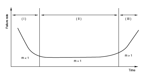
Product's failure rate throughout its lifetime is depicted as a bathtub curve, as shown below. Failure rate is high at the beginning and end of its service lifetime.
The high failure rate in the initial failure period is derived from latent design errors, process errors, and many other causes. This process is called debugging, performing aging or screening in order to find out initial failures.
The initial failure period is followed by a long period with low, stable failure rate. In this period, called accidental failure period, failures occurs at random along the time axis. While zero accidental failure rate is desirable, this is actually not practical in the real world.
In the final stage of the product's service lifetime comes the wear-out failure period, in which the life of the product expires due to wear of fatigue. Preventive maintenance is effective for this type of failure. The timing of a relay's wear-out failure can be predicted with a certain accuracy from the past record of uses. The use of a relay is intended only in the accidental failure period, and this period virtually represents the service lifetime of the relay.
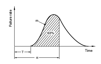
Weibull analysis is often used for classifying a product's failure patterns and to determine its lifetime.
Weibull distribution is expressed by the following equation:
m: Figure parameter
α: Measurement parameter
γ: Position parameter
Weibull distribution can be adopted to the actual failure rate distribution if the three variables above are estimated.
The Weibull probability chart is a simpler alternative of complex calculation formulas. The chart provides the following advantages:
(1) The Weibull distribution has the closest proximity to the actual failure rate distribution.
(2) The Weibull probability chart is easy to use.
(3) Different types of failures can be identified on the chart.
The following describes the correlation with the bathtub curve. The value of the parameter " m " represents the type of the failure.
(1) When m < 1: Initial failures
(2) When m = 1: Accidental failures
(3) When m > 1: Wear-out failures
Relays, Couplers, Connectors, Switches, and Other
Control Components & Electronic Device Products
FA Sensors, PLC ,Eco Power Meters, Times, Counters, Limit Swicheds and Other FA Sensors & Components
Contact UsMotors for FA & Industrial Application, Motors for Appliance & Automotive
Contact Us* The term 'specific products' refers to tactile switches (light-touch switches), detector switches, push switches, encoders, rotary volume controls, position sensors, and touch panels.