Here is PDF of this page.
Power storage system

1. For Charge and Discharge
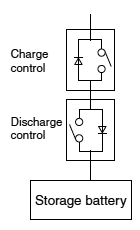
AQ-A SSR (PhotoMOS®) is used to switch charge and discharge. We recommend solid state relays for applications where there will be frequent ON/OFF switching.
 | 1. Regular operation
Turn ON both solid state relays for charge and discharge control. Current flows in both directions. 2. Over-charge prevention
In order to prevent over charging, the solid state relay on the charge control side turns OFF. On the discharge side, current will flow because there is a diode. 3. Over-discharge prevention
In order to prevent over discharging, the solid state relay on the discharge control side turns OFF. On the charge side, current will flow because there is a diode. |
Charge and discharge control is possible by effectively utilizing the internal diodes of the solid state relay.
*If you want to use charge and discharge control by internal diodes please contact our sales team.
(Maximum switching capacity differs from output section.) | 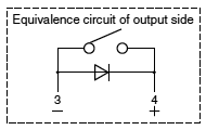 |
2. For preventing an inrush current into capacitors when charging (pre-charge circuit)
AQ-A SSR (PhotoMOS®), HE-V relay, and 10A and 20A types of EP relays are used for preventing an inrush current into capacitors when charging. We recommend solid state relays for miniaturization and HE-V relay and 10A and 20A types of EP relays for high voltages.
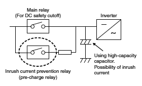
During device startup, the inrush current prevention relay turns ON and the main relay turns ON after the capacitor is charged.
Effective for protection against inrush currents that occur when charging the capacitor.
3. For Insulation Detection
PhotoMOS® are used for monitoring storage battery units for insulation deterioration. If the insulation in a unit deteriorates, a ground-fault current passes when the relay is turned ON, and a sensor detects the current. High load voltage type PhotoMOS® are ideal for use with storage batteries, which carry high voltage.
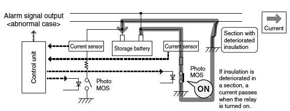
Inside of a storage battery unit
| When insulation of high voltage area and chassis is deteriorated | 1. PhotoMOS is turned on.
2. The current sensor detects a ground-fault current.
3. An alarm signal is output. |
4. For Battery Monitoring
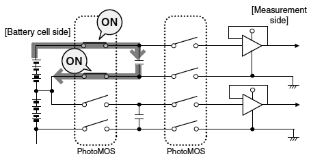
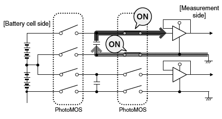
PhotoMOS® are used in a circuit for monitoring charging voltages of a battery cell group. Compact PhotoMOS® capable of frequent switching are ideal for this type of use. Use of the relays allows for insulation from high voltage areas.
When charging the capacitor
1. PhotoMOS® on the battery cell side are turned ON.
2. The capacitor is charged. |
When measure
1. PhotoMOS® on the battery cell side are turned OFF.
2. PhotoMOS® on the measurement side are turned ON.
3. The voltage of capacitor (= voltage of battery cell group) is measured. |
Smart meters

1. For Driving Main Relays
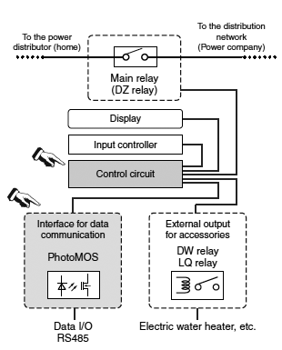
PhotoMOS® and AQ-H SSRs are used for driving main relays. (Load voltage: 60V type)
2. For Data Communications
PhotoMOS® are used as output contacts for external communications. (Load voltage: 350V/400V type)
3. Mechanical relay application circuit example: For Main Power Cutoff
Main relays are used for cutting off the main power. There is demand for a remote cutoff function for rolling blackouts, a prepaid system, safety measures, responses to non-payment of electric bills, etc. (Recommended products: DZ relay)
4. For External Output of Accessories
Relays are used for driving a contactor to turn on a electric water heater using power at night.
(Recommended products: DW and LQ relays)
Automatic meter reading
By the end of fiscal 2015, the number of domestic smart meters installed by Japanese power companies reached more than 10 million units. PhotoMOS® are capable of controlling from low level signals up to power signals and feature low leakage current and noise.

Medical equipment
Medical equipment which processes low level signals includes electrocardiographs, electroencephalographs, and X-ray CT scanners.
PhotoMOS® accurately transfer low level signals (less than several hundred millivolts).
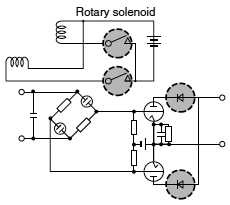
Furthermore, they are also convenient in driving rotary solenoids such as those used to automatically switch voltage ranges.
Security Equipment
There are many types of security systems from home and office security to building security.
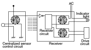
PhotoMOS® are ideal for use as input interfaces for system sensors and output interfaces for alarms.
Input interface: Low leakage current makes use possible for low level voltage and current input.
Output interface: Outputs either AC or DC up to a load voltage of 400 V.
Telecommunications
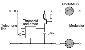
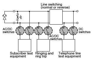
A variety of signals, with levels from millivolts (at microamperes) to tens of volts (at several hundred milliamperes), AC or DC, and even high bit-rate signals, can be superimposed on telephone lines, the heart of telecommunication networks. The switches in telecommunication circuits, which normally carry DC signals, also carry AC signals on top of the DC level when an intermittent signal (e.g. ringer signal) is being sent. PhotoMOS® are capable of controlling small level (millivolts at microamperes) AC or DC signals.
Communications equipment
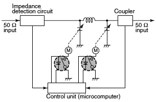
The future of communications is in satellite communications. Satellite-communications feature many advantages such as indifference to terrestrial disasters, wide service areas, simple circuit modification and simultaneous conversations. An important control operation in communications equipment is fast automatic tuning.
PhotoMOS® can easily be connected in parallel, difficult with conventional transistor type. As a result, a variety of circuit connection are possible and power circuits can also be designed.
OA equipment
OA equipment usually contains a sensor control unit (for temperature, speed, torque, etc.), drive unit, power supply unit, and a processing unit which controls the overall system. It is organized similarly to compact factory automation machinery. PhotoMOS® have wide application in the interfaces for signals which connect the functions of these units.
- Operates on a 24 mW input to enable direct control of C-MOS devices.
- Signal transfer through optical coupling achieves high resistance to noise and transients, eliminating the need for adding a snubber circuit to the output to control the load voltage.
- Advantages in the total cost and reliability in the control system result from the absence of AC leakage current related to the snubber circuit.

Instrumentation
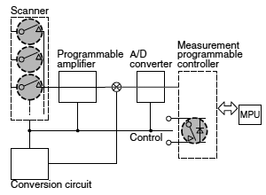
With the spread of microcomputer chips, the latest instruments are required to measure a variety of signals at high speeds under various conditions. PhotoMOS® are recommended for measurement scanning functions, automatic zero-point compensation to eliminate zeropoint error, and measurement sequence interfaces (e.g. alarm interface.)
Programmable controller
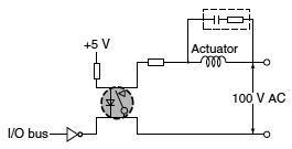
The output circuit of a programmable controller requires various interfaces to match the load type. Recently, as the computing speed and data processing speed increase, problems may arise from noise at the input interface as well as at the output interface.
PhotoMOS® are resistant to inrush current (due to phase shift) and eliminate the need for snubber circuits as long as they are operated within the ratings. Furthermore, use of PhotoMOS® decreases the mounting area requirements, resulting in more compact programmable controllers.
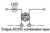
Application Examples
1. High Response Speed
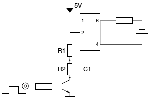
Vcc = 5 V
R1 = 47 Ω
R2 = 180 Ω
C1 = 2.2 μF
Measurements for AQV204(400V) AC/DC Type
| Turn on time at 10 mA LED current | 0.18 ms |
| Turn on time with speed-increase capacitor (LED current 45 mA) | 0.03 ms |
2. Microprocessor System I/O Board

3. Dial Pulse Generator
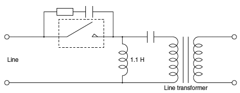
4. Capacitor Switch Circuit

5. Scanner
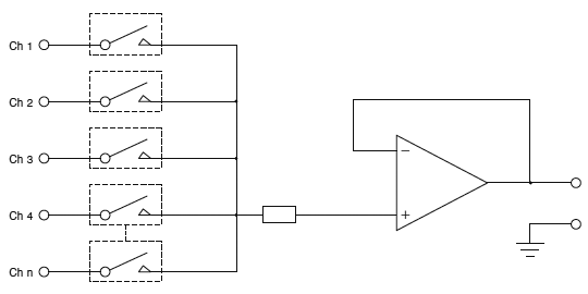
PhotoMOS Related Information


